

Antenna device and manufacturing method of antenna device
- Summary
- Abstract
- Description
- Claims
- Application Information
AI Technical Summary
Benefits of technology
Problems solved by technology
Method used
Image

Examples
embodiment no.1
Another-Embodiment No. 1
[0082]FIG. 9 is a perspective view showing a constitution of an antenna device 11 relating to Another-Embodiment No. 1. FIG. 10 is a perspective view showing a constitution in which the resin-filling portion 50 is removed from the antenna device 11 relating to the Another-Embodiment No. 1. It should be noted in the constitution shown in FIG. 9 that there is shown a state in which the side surface on the front side (Y1 side) of the case 60 is opened, but it is needless to say that the side surface on this front side (Y1 side) can be closed.
[0083]As shown in FIGS. 9 and 10, in the Another-Embodiment No. 1, the terminal members 70 are different from those shown in FIG. 7 and are formed in straight shapes. Then, the terminal members 70 of such straight shapes are plugged-in into the first mounting vertical-groove 83A and the second mounting vertical-groove 83B. Caused by the relation in which the terminal members 70 of such straight shapes are plugged-in into the...
embodiment no.2
Another-Embodiment No. 2
[0084]FIG. 11 is a perspective view showing a constitution of an antenna device 12 relating to Another-Embodiment No. 2. FIG. 12 is a perspective view showing a state in which the resin-filling portion 50 is removed from the antenna device 12 relating to the Another-Embodiment No. 2. It should be noted in FIG. 11 that there is shown a state in which the end surface of one end side (X1 side) in the longitudinal direction (X-direction) is opened, but it is needless to say that the end surface of this one end side (X1 side) can be closed.
[0085]As shown in FIG. 12, in the Another-Embodiment No. 2, the terminal members 70 are bent so as to get approximate L-shapes similarly as the terminal members 70 shown in FIG. 7. However, the portions which are plugged-in into the first mounting vertical-groove 83A and the second mounting vertical-groove 83B within the terminal members 70 are constituted to be straight shapes. Then, each of the terminal members 70 is bent on t...
embodiment no.3
Another-Embodiment No. 3
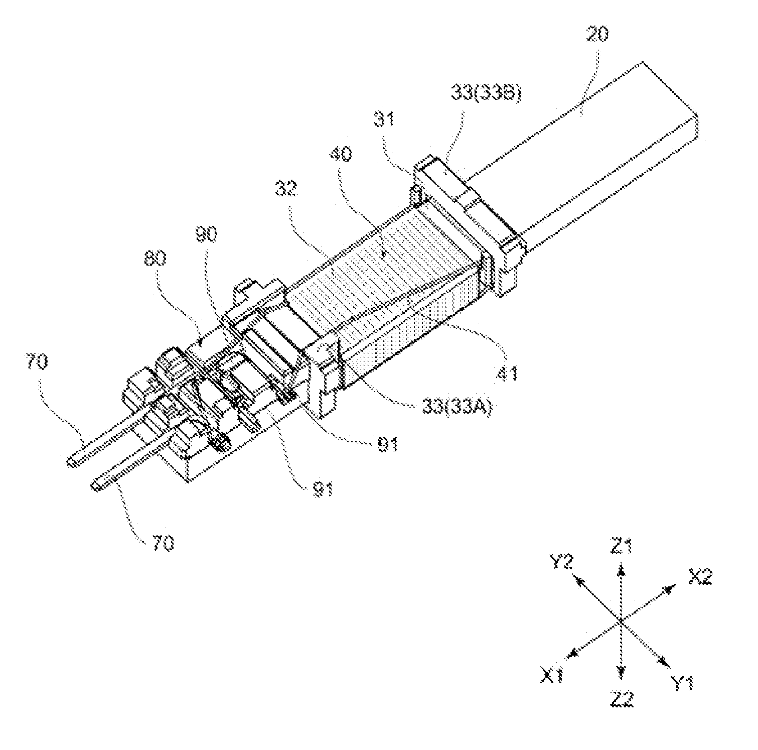
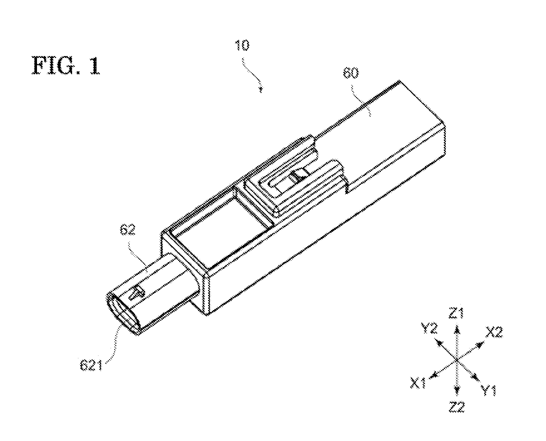
[0086]FIG. 13 is a perspective view showing a constitution obtained by removing the case 60 and the resin-filling portion 50 from the constitution of the antenna device 13 relating to Another-Embodiment No. 3. It should be noted in this Another-Embodiment No. 3 that the constitution of the state of mounting the case 60 and the resin-filling portion 50 is similar to the configuration shown in FIG. 1 which was described above and therefore, the drawing thereof is omitted.
[0087]Such an antenna device 13 is formed as an antenna device of three-terminal type in which there are used three terminal members 70. Then, in order to get correspondence with such three terminal members 70, there are provided three mounting horizontal-grooves 82 and likewise three mounting vertical-grooves 83 for the grooves 81 which exist in the terminal mounting unit 80. In the following explanation, with regard to the mounting horizontal-grooves 82, there will be named as a first mountin...
PUM
 Abstract
Description
Claims
Application Information