
Vehicle

Active Publication Date: 2015-10-29
YAMAHA MOTOR CO LTD
View PDF14 Cites 10 Cited by
  • Summary
  • Abstract
  • Description
  • Claims
  • Application Information

AI Technical Summary

Benefits of technology

The present invention is about a vehicle that can lean and has two front wheels. This design helps prevent the vehicle from becoming bigger as it includes additional components.

Problems solved by technology

This limits the possibility of making the movable outer edge of the cross portion small.
Because of this, the inventors have discovered that avoiding interference with the front cross portion makes it difficult to enlarge the front portion of the vehicle even though the vehicle component is disposed at the front portion of the vehicle.
Additionally, the inventors have noticed that a through portion is easily located inward of the movable outer edge of the cross portion by making use of the original large shape of the cross portion that has conventionally been considered as a disadvantage when devising the shape of the cross portion.

Method used


Image

  • Vehicle
  • Vehicle
  • Vehicle

Examples


modified examples

[0138]While the present invention has been described heretofore with respect to preferred embodiments thereof, the technical scope of the present invention is not limited to the technical scope that is descriptively defined in the preferred embodiments of the present invention. Those skilled in the art to which the present invention pertains will recognize that various alterations or improvements may be made to the preferred embodiments of the present invention. Referring to FIGS. 7 to 12, additional preferred embodiments of the present invention will be described below.

first modified example

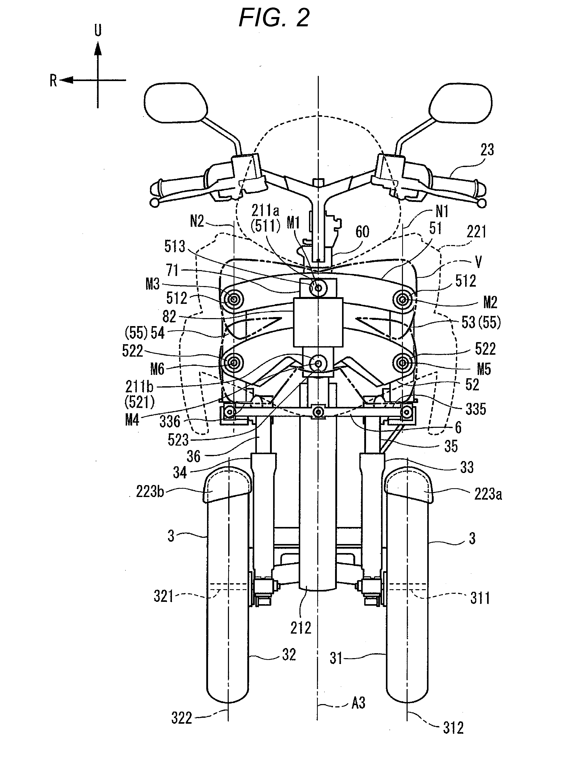
[0139]In the preferred embodiments described above, the first penetrating portion 211a is described as preferably penetrating the first through hole 513 that includes the turning axis of the upper cross portion 51 and the second penetrating portion 211b penetrates the second through hole 523 that includes the turning axis of the front lower cross portion 52A. However, the present invention is not limited to this example.

[0140]FIG. 7 is a view showing an upper cross portion 151, a front lower cross portion 152, a left side portion 53, a right side portion 54, and a hydraulic unit 82 that results when these elements are seen from the direction of an upper middle axis M1, and a headstock 211 is omitted from illustration. For example, as in a vehicle according to a modified example shown in FIG. 7, a configuration may be used in which first penetrating portions penetrate positions on the first upper cross section 151 where turning axes of the upper cross portion 151 do not pass and seco...

second modified example

[0149]FIGS. 8A to 8C are views depicting a second modified example of a preferred embodiment of the present invention. FIG. 8A is a side view showing a headstock 211, an upper cross portion 251, a lower cross portion 252, an attaching bracket 7, and a hydraulic unit 82 that is an example of a vehicle component of a vehicle according to the second modified example. FIG. 8B is a view that results from viewing FIG. 8A from the direction of an upper middle axis M1. FIG. 8C is a view in which the upper cross portion 251 and the lower cross portion 252 are removed from FIG. 8B.

[0150]In this modified example, as shown in FIG. 8A, both the upper cross portion 251 and the lower cross portion 252 are disposed forward of the headstock 211. A relatively wide space is provided between the upper cross portion 251 and the lower cross portion 252 in relation to an up-and-down direction of a body frame 21. A front movable outer edge V1 that is defined by the upper cross portion 251 and a front movab...


PUM


Abstract

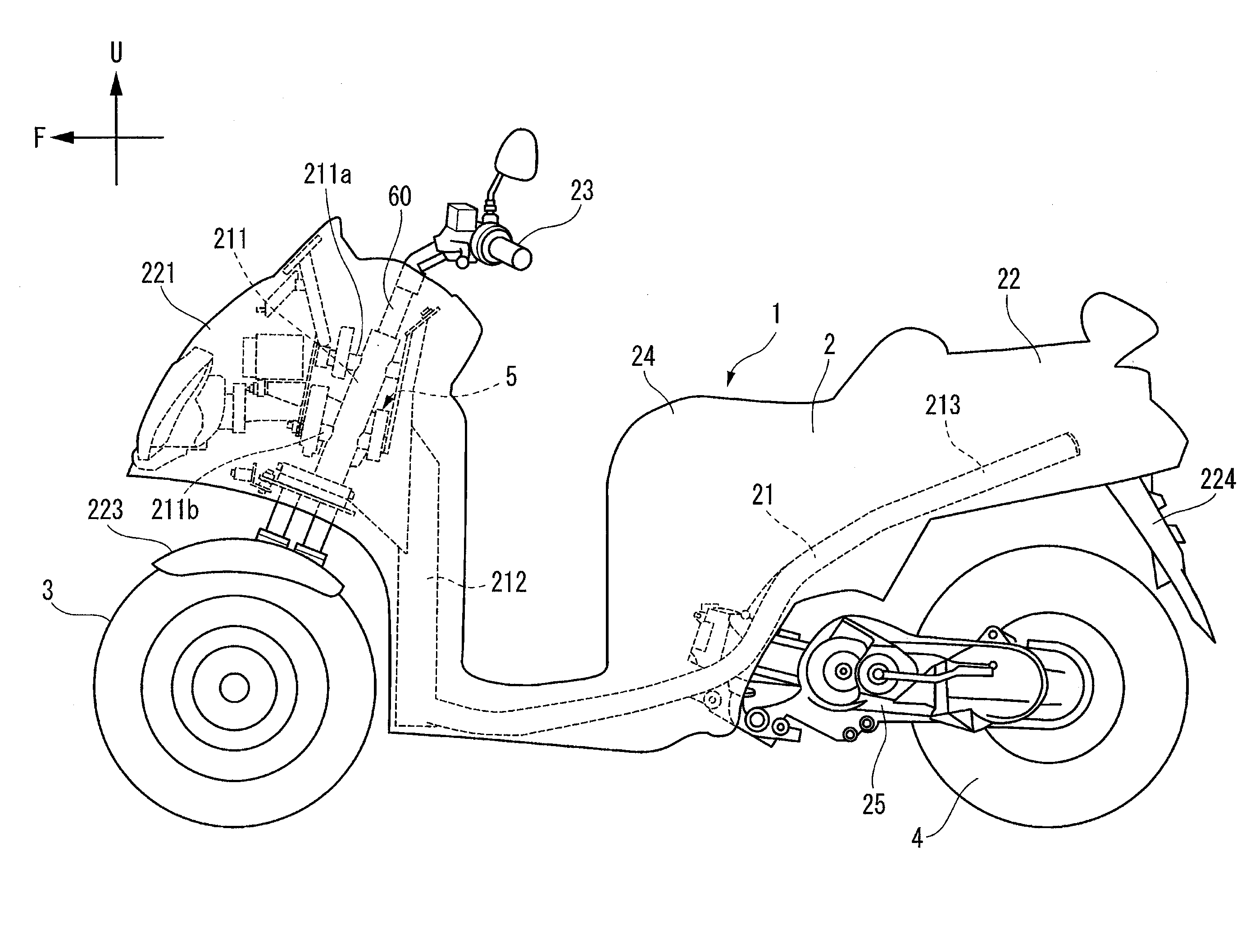
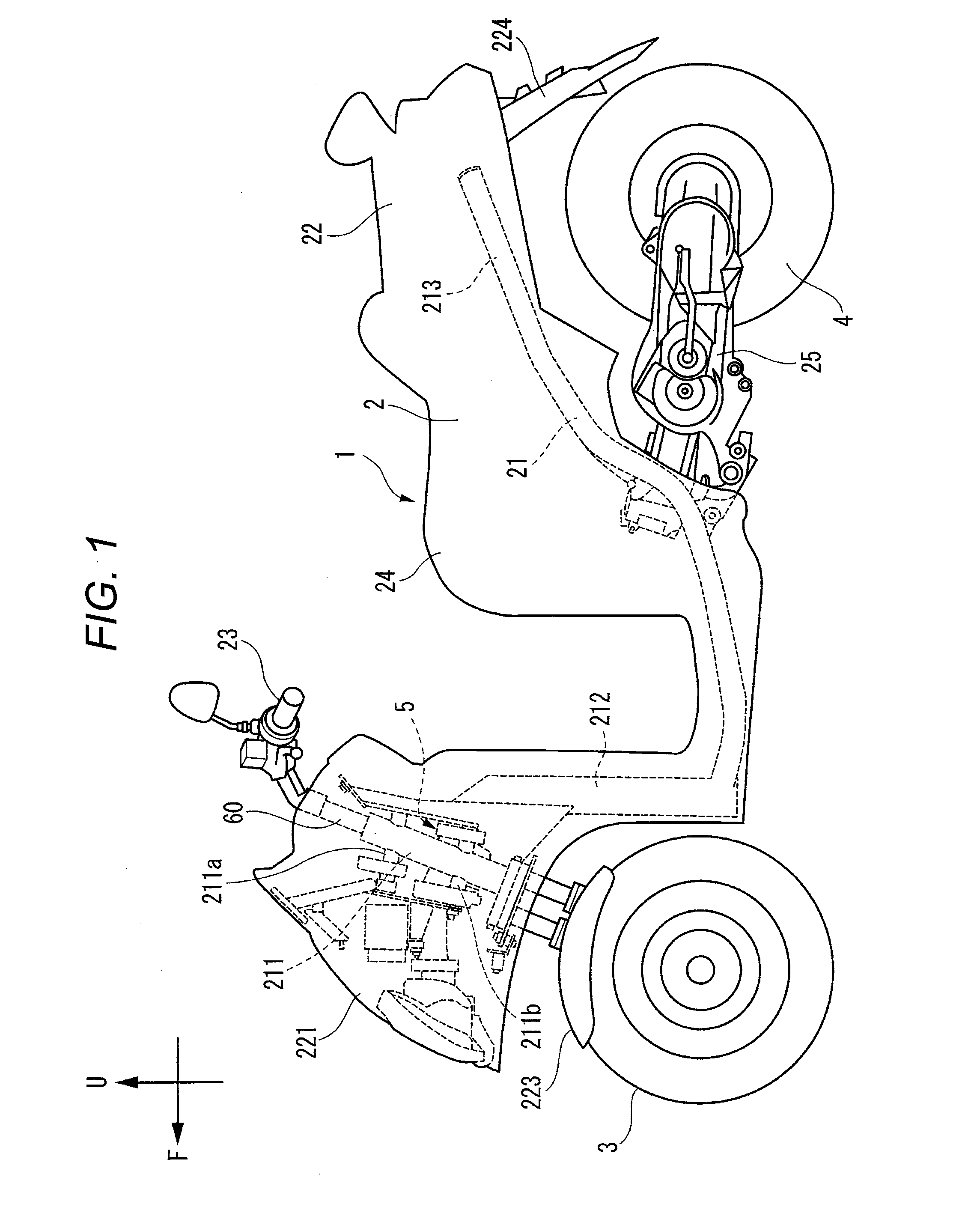
A vehicle includes a body frame, a left front wheel and a right front wheel, a link mechanism configured to be deformed as a vehicle body leans, and vehicle components disposed directly forward of the link mechanism in relation to a front-and-rear direction of the vehicle. The vehicle components are supported on the body frame via penetrating portions that extend from the body frame toward the front of the vehicle and penetrate the link mechanism.

Description

BACKGROUND OF THE INVENTION[0001]1. Field of the Invention[0002]The present invention relates to a vehicle that includes a body frame that can lean and two front wheels.[0003]2. Description of the Related Art[0004]Vehicles including a body frame that can lean and two front wheels are known in Catalogo partidi ricambio, MP3 300 64102 ie LT Mod. ZAPM64102, Piaggio; U.S. Design Pat. No. 547,242 and the like. In the vehicle described in Catalogo partidi ricambio, MP3 300 64102 ie LT Mod. ZAPM64102, Piaggio on which a link mechanism is mounted, vehicle components such as a radiator, a headlamp and the like are disposed directly forward of the link mechanism.[0005]In the vehicles described in Catalogo partidi ricambio, MP3 300 64102 ie LT Mod. ZAPM64102, Piaggio and U.S. Design Pat. No. 547,242, the link mechanism is disposed not between the right front wheel and the left front wheel but above the right front wheel and the left front wheel. This configuration prevents the enlargement of a...

Claims


Application Information

Patent Timeline
IPC IPC(8): B62K5/10B62K5/027B62K5/08
CPCB62K5/10B62K2005/001B62K5/027B62K5/08B62K5/05B60G2300/122B60G2300/45B62K19/38B62K25/04B62D9/02
Inventor IIZUKA, TOSHIOHIRAYAMA, YOSUKE
Owner YAMAHA MOTOR CO LTD
Learn More