Adjustable scanner mounting assembly and method

Active Publication Date: 2015-11-05
METTLER TOLEDO INC
View PDF32 Cites 0 Cited by
  • Summary
  • Abstract
  • Description
  • Claims
  • Application Information

AI Technical Summary

Benefits of technology

[0006]System and method embodiments of the invention permit a variety of scanners to be easily and quickly installed into a given scale/scanner device, and at different orientations. Such scanners may include, without limitation, laser-based scanners that emit laser light to scan a bar code and optical-type scanners that essentially capture electronic images of a barcode. Optical-type scanners are now also frequently being referred to in the art as “imagers”, and for purposes of the present application, the term “scanner” or “scanners

Problems solved by technology

There has heretofore been no efficient way of installing different scanners into a given scale/s

Method used


Image

  • Adjustable scanner mounting assembly and method
  • Adjustable scanner mounting assembly and method
  • Adjustable scanner mounting assembly and method

Examples


Embodiment Construction

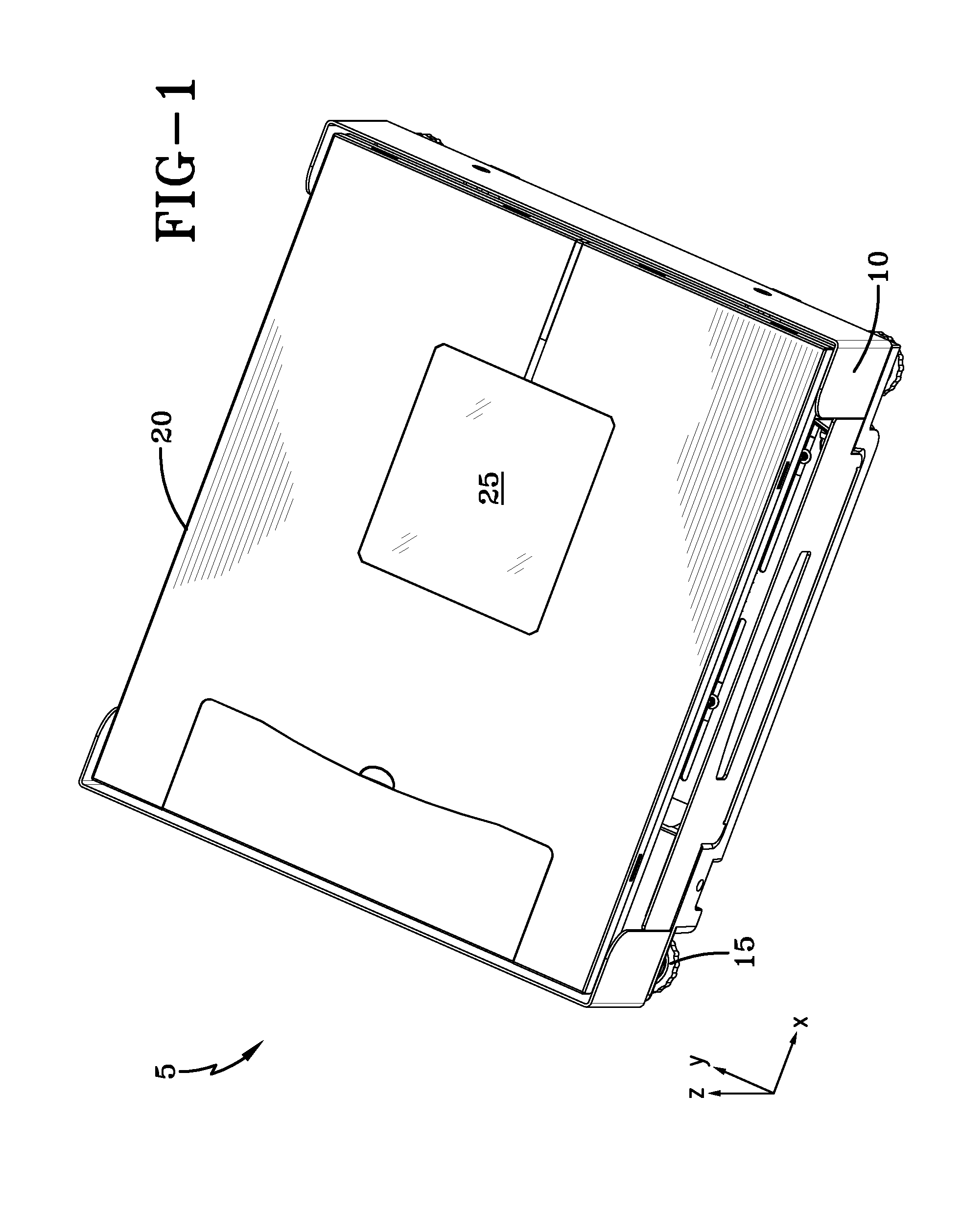
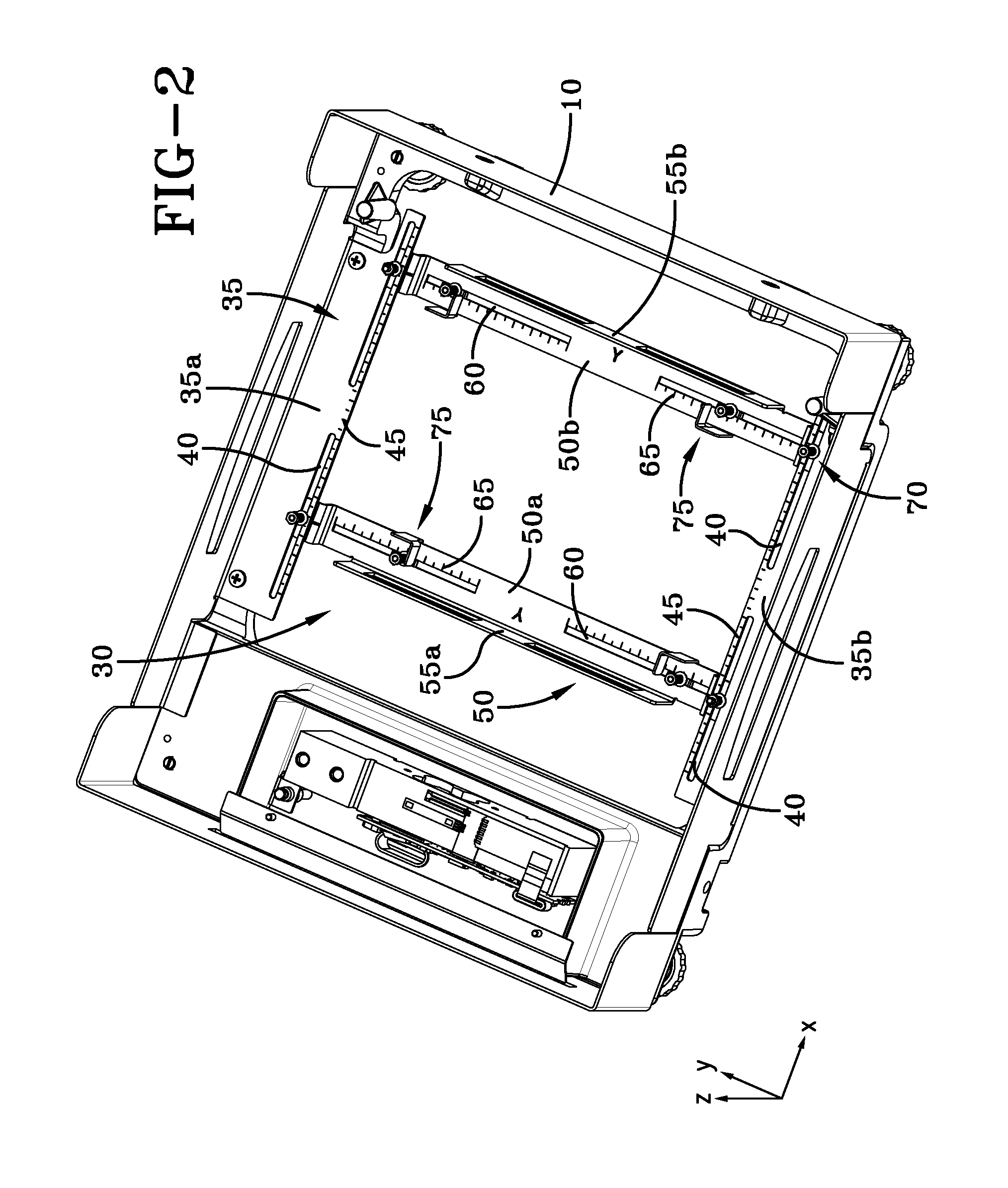
[0025]Depicted in FIG. 1 is one exemplary embodiment of a recessed installation type scale / scanner device 5 to which scanner mounting assembly embodiments of the invention may be installed. As shown, this particular scale / scanner device 5 includes a housing 10, with leveling feet 15 located along a bottom surface thereof. A scale platter 20 that includes a glass scanner viewing window 25 forms a top surface of the scale / scanner device 5. In use, items having bar codes to be scanned are passed over the scanner window 25 for scanning by a subjacent scanner (not shown), while items to be weighed are placed on the scale platter 20 that typically rests on load cells or some other weighment element(s), as is well known in the art and generally described above.

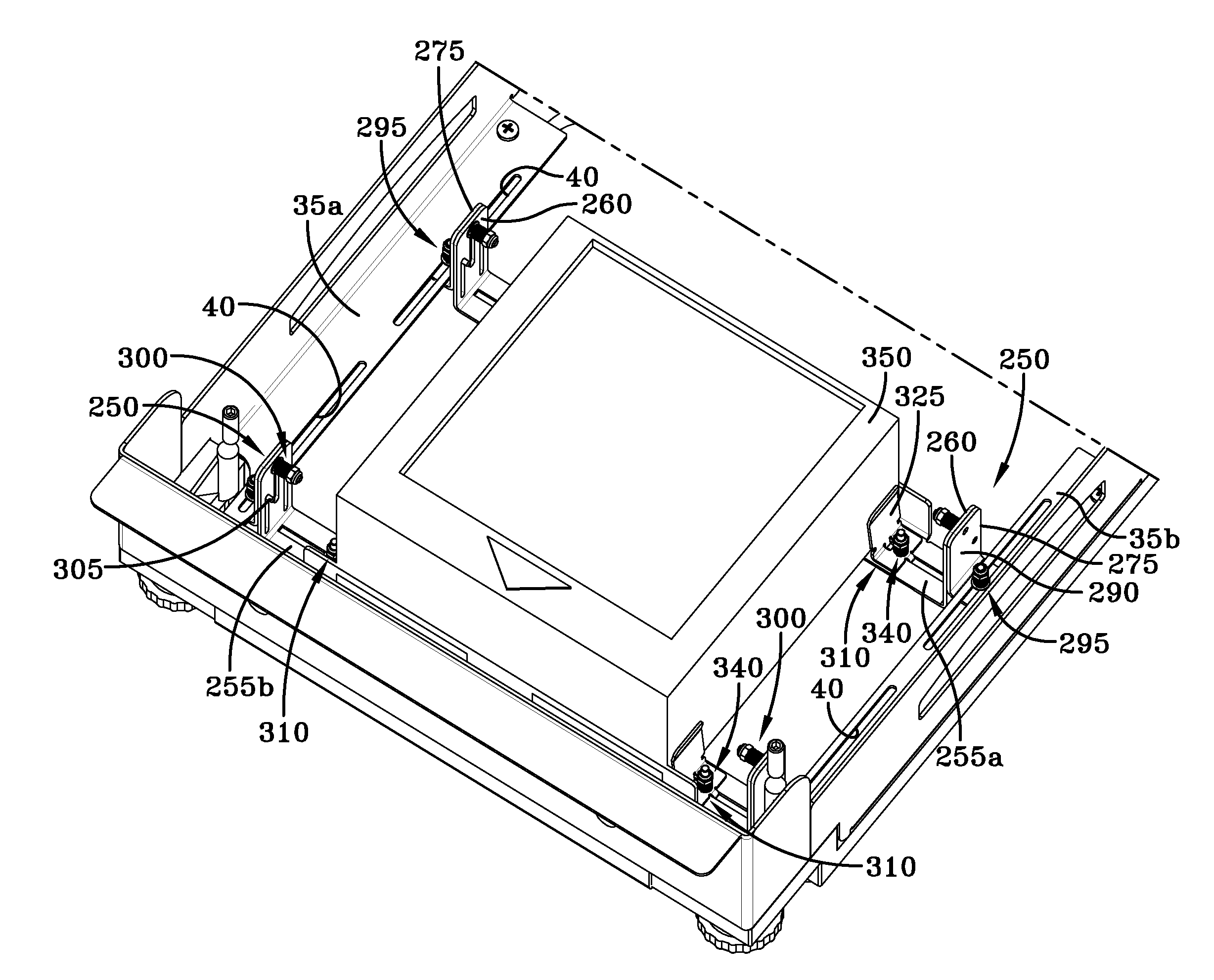
[0026]A section view of the scale / scanner device 5 of FIG. 1 is illustrated in FIG. 2. The view of FIG. 2, as well as the views provided by FIG. 3 and FIG. 4, reveal one exemplary embodiment of a scanner mounting assembly 30 that is ...


PUM


Abstract

Assemblies and methods for adjustably mounting scanners in scale/scanner devices, and scale/scanner devices employing such assemblies.

Description

TECHNICAL FIELD[0001]Embodiments of the invention are directed to assemblies and methods for adjustably mounting scanners in scale / scanner devices, and to scale / scanner devices employing such assemblies.GENERAL BACKGROUND[0002]Those of skill in the art, as well as laypersons, are no doubt familiar with barcode scanners such as those that are located, for example, at a point-of-sale (POS) location within a retail establishment. Variations of these scanners exist and may include, for example, laser-based scanners that emit laser light to scan a bar code and optical-type scanners that essentially capture electronic images of a barcode. Such scanners are often integrated with a weighing scale. In some embodiments, such a combination scale / scanner device may include an enclosure that extends upward from a POS countertop to house the scale and scanner components. In other embodiments of such a device, the majority of the scale / scanner may be recessed within a cutout that is located in the...

Claims


Application Information

Patent Timeline
IPC IPC(8): A47F9/04F16M13/02H05K5/02
CPCA47F9/04A47F2009/041F16M13/022H05K5/0217G01G19/4144G01G21/23G01G21/28A47F9/046
Inventor HAGGLUND, CURTISYEAUGER, GARYBENNETT, RICHARDKELLY, STEVE
Owner METTLER TOLEDO INC
Why Eureka
Try Eureka