
Carrying plate for breathing apparatus

a technology for carrying breathing apparatuses and back plates, which is applied in the field of carrying back plates for breathing apparatuses, can solve the problems of reducing affecting the service life of users, so as to achieve the effect of quick and easy removal of the back plate and the associated supply line, and reducing the time consumption of users

Active Publication Date: 2016-08-18
SCOTT HEALTH & SAFETY
View PDF12 Cites 0 Cited by
  • Summary
  • Abstract
  • Description
  • Claims
  • Application Information

AI Technical Summary

Benefits of technology

The mounting assembly described in this patent allows a tank and valve to be securely attached to a user's jacket or clothing, allowing for easy removal without having to remove or discard the jacket. The straps and back plate are attached with quick release systems, making it easy for the user to remove the tank and valve assembly if not needed. The back plate is made of light weight, low-profile material and specialist mountings allow for pneumatics to be quickly mounted to the back plate, even for multiple tank sizes. The technical effect is a more comfortable and versatile mounting system for SCBA equipment.

Problems solved by technology

Known carrying assemblies may be time consuming to don and remove, which can be a significant issue in certain situations.
Furthermore, the shoulder and waist straps may extend tightly around the user, which may restrict both the movement of the user and also the user's accessibility to other equipment on the user's person.
Many current SCBA's are designed for the firefighting industry and do not integrate very well with other types of body worn equipment in other industries.

Method used


Image

  • Carrying plate for breathing apparatus
  • Carrying plate for breathing apparatus
  • Carrying plate for breathing apparatus

Examples


Embodiment Construction

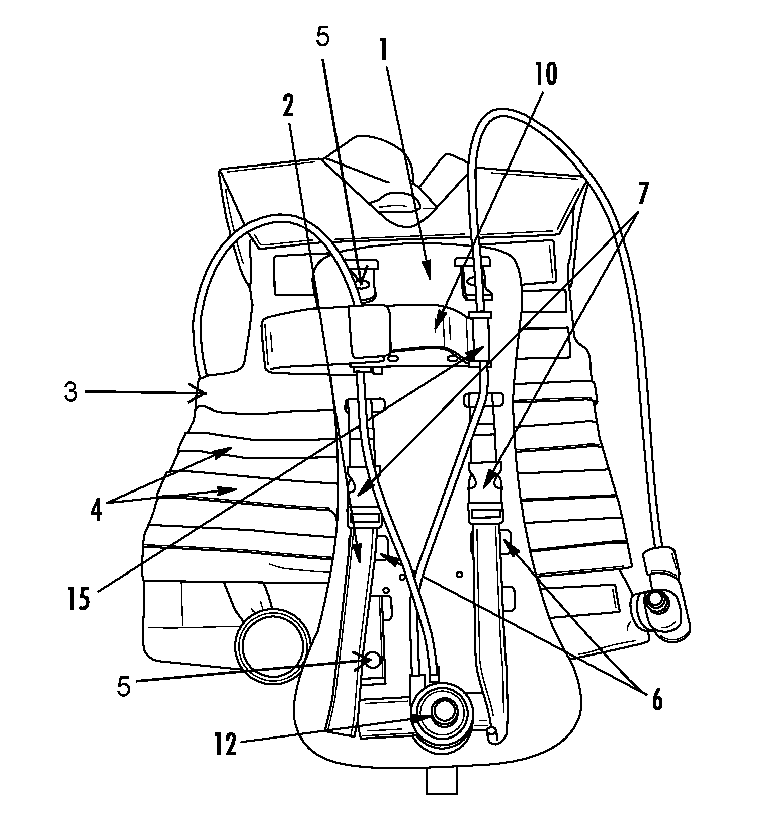
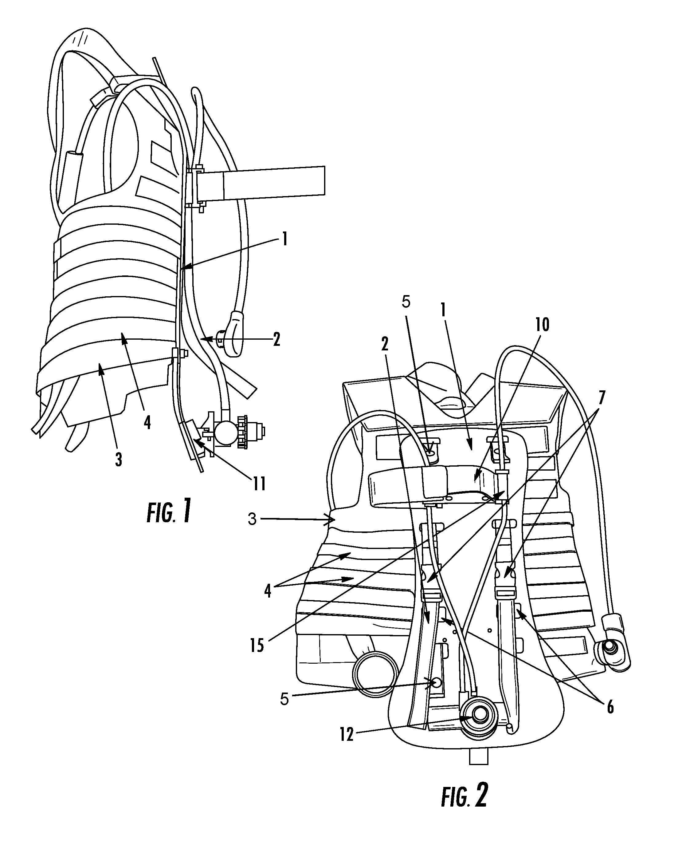
[0022]FIG. 1 is a side view of a bullet proof jacket with a mounting assembly formed in accordance with an embodiment. The mounting assembly includes a back plate 1 mounted by MOLLE straps 2 to a body armour jacket 3. The jacket 3 has horizontal webbing straps 4 which extend around the jacket 3. The webbing straps 4 are fastened to the jacket 3 at aligned intervals, forming aligned points or gaps at which the MOLLE straps 2 may be fed vertically through the webbing straps 4 between each strap and the jacket 3. Referring now to FIG. 2, the MOLLE straps 2 are attached to the back plate 1 at the top and bottom by press studs 5. The press studs 5 enable the user to easily detach the top and / or bottom of each MOLLE strap 2 from the back plate 1 to release the back plate 1 and any equipment mounted thereon from the jacket 3 while wearing the jacket 3. Although press studs 5 are shown in FIG. 2, it is understood that other releasable fasteners for fastening the MOLLE straps 2 to the back p...


PUM


Abstract

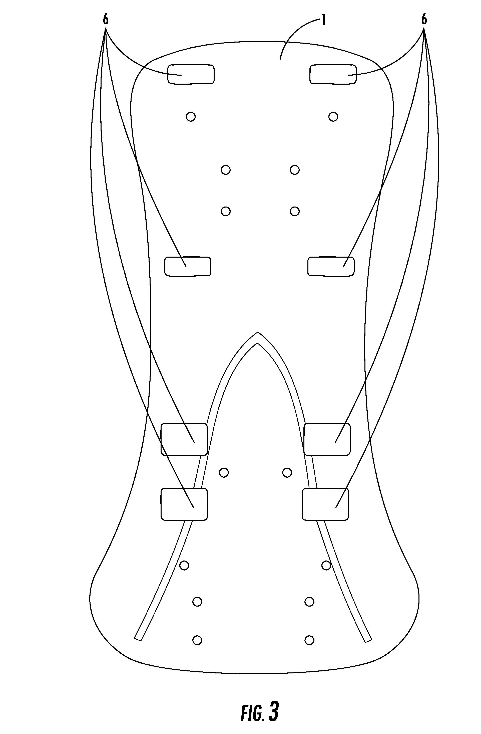
A mounting assembly for a self-contained breathing apparatus (SCBA) includes a back plate defining a plurality of apertures therethrough arranged in first and second columns. The apertures in the columns are sized and spaced to receive corresponding first and second mounting straps woven therethrough that are configured to extend around webbing straps of a carrying jacket to fasten the back plate to the carrying jacket. The back plate includes a first press stud associated with the first column and a second press stud associated with the second column, which are configured to engage ends of the respective first and second mounting straps to releasably secure the mounting straps to the back plate. A tank securing strap on the back plate releasably fastens a supply tank to the back plate. A valve retaining mount on the back plate releasably secures an air supply valve for engagement with the supply tank.

Description

CROSS-REFERENCE TO RELATED APPLICATIONS[0001]The present application is a continuation of U.S. patent application Ser. No. 14 / 509,684 (the “'684 Application”), which was filed Oct. 8, 2014 and is incorporated by reference in its entirety. The '684 Application claims priority to International Application No. PCT / GB2014 / 052915 (the “'915 Application”), filed Sep. 26, 2014, which claims priority to Great Britain Patent Application No. GB 1317249.9 (the “'249 Application”), filed Sep. 27, 2013. Both the '915 Application and the '249 Application are hereby incorporated by reference in their entirety.BACKGROUND OF THE INVENTION[0002]The subject matter described and / or illustrated herein relates generally to harness plates for carrying breathing apparatuses, such as air tanks and associated equipment.[0003]Self-contained breathing apparatuses (SCBA) are used in a variety of situations where an individual and safe supply of breathable air is required by a user, such as by firefighters enter...

Claims


Application Information

Patent Timeline
Patent Type & Authority Applications(United States)
IPC IPC(8): A62B9/04A62B9/02A62B25/00
CPCA45F2200/00A45F2200/0566A62B9/04A45F2003/146A62B9/02A62B25/00A45F3/10
Inventor LANGFORD, GRAHAMKEARNS, JOHN PATRICKSUTTON, ROBERT C.
Owner SCOTT HEALTH & SAFETY
Learn More