Rotor hub of a wind turbine, and method for assembling such a rotor hub

a technology of wind turbine and rotor hub, which is applied in the manufacture of engines, mechanical equipment, machines/engines, etc., can solve the problems of difficult access to control devices from the interior of the hub housing, the complication of assembly of control devices, and the difficulty of effected control devices after installation, so as to achieve simplified assembly of electrical control devices and facilitate access to electrical control devices from within the hub housing

Active Publication Date: 2021-03-18
WOBBEN PROPERTIES GMBH
View PDF2 Cites 1 Cited by
  • Summary
  • Abstract
  • Description
  • Claims
  • Application Information

AI Technical Summary

Benefits of technology

[0007]One or more embodiments are directed to a rotor hub of the kind set forth in the opening part of this specification such that assembly of the electrical control devices is simplified. Accessibility to the electrical control devices from within the hub housing, for example for maintenance purposes, is improved.
[0008]One embodiment is directed to a rotor hub of a wind turbine comprising a hub housing which has a plurality of connecting flanges which are each adapted for connection of a rotor blade, wherein each of the rotor blades is coupled to a pitch drive for rotating the rotor blade, wherein the pitch drive is connected to an arrangement of electrical control devices which are adapted to control the pitch drive. The arrangement of the control devices is provided in a module in the form of a structural unit, wherein the module is connected as a whole to the hub housing. The pre-assembly of the electrical control devices to constitute a module as a structural unit can be effected completely outside the rotor hub so that sufficient space is available for mounting the control devices to the module and both fixing to the module and also the cabling for the control devices to each other can be quickly and easily effected as necessary by the assembly operative without space restrictions.
[0009]The module preferably has an interface for fixing to the respective connecting flange of the rotor hub. The interface is preferably a drilling or screw pattern correspondingly provided both on the connecting flange and also the module. The interface is preferably such that assembly of the module can be effected in exactly one orientation. That averts the risk of faulty assembly or defective orientation of the module on the rotor hub.

Problems solved by technology

By virtue of the working volume which is only limitedly available there on the one hand, assembly of the control devices has been linked to a certain degree of complication and effort.
On the other hand, the control devices after installation has been effected are not always readily accessible in operation so that there is seen to be a need for improvement in that respect.
In regard to this design configuration also later accessibility to the control devices from the interior of the hub housing was difficult and assembly was also completed in a large number of installation steps.

Method used


Image

  • Rotor hub of a wind turbine, and method for assembling such a rotor hub
  • Rotor hub of a wind turbine, and method for assembling such a rotor hub
  • Rotor hub of a wind turbine, and method for assembling such a rotor hub

Examples


Embodiment Construction

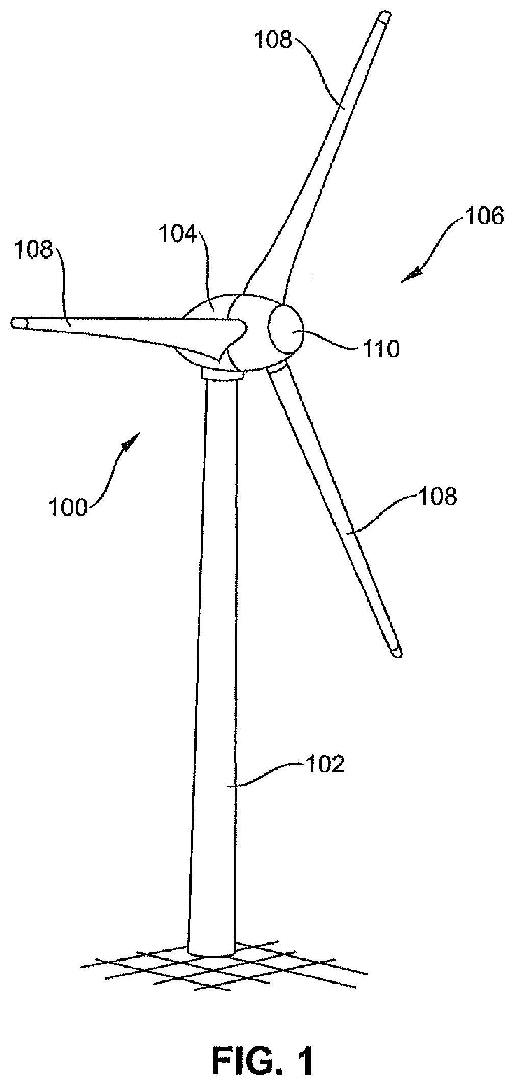
[0037]FIG. 1 shows a wind turbine 100 comprising a tower 102 and a nacelle 104. Arranged on the nacelle 104 is a rotor hub 1 having three rotor blades 108 and (optionally) a spinner 110. The rotor blades 108 are arranged with their rotor blade root on a rotor hub. The rotor hub 1 is driven in rotation in operation by the wind and thereby drives a generator (not shown) in the nacelle 104.

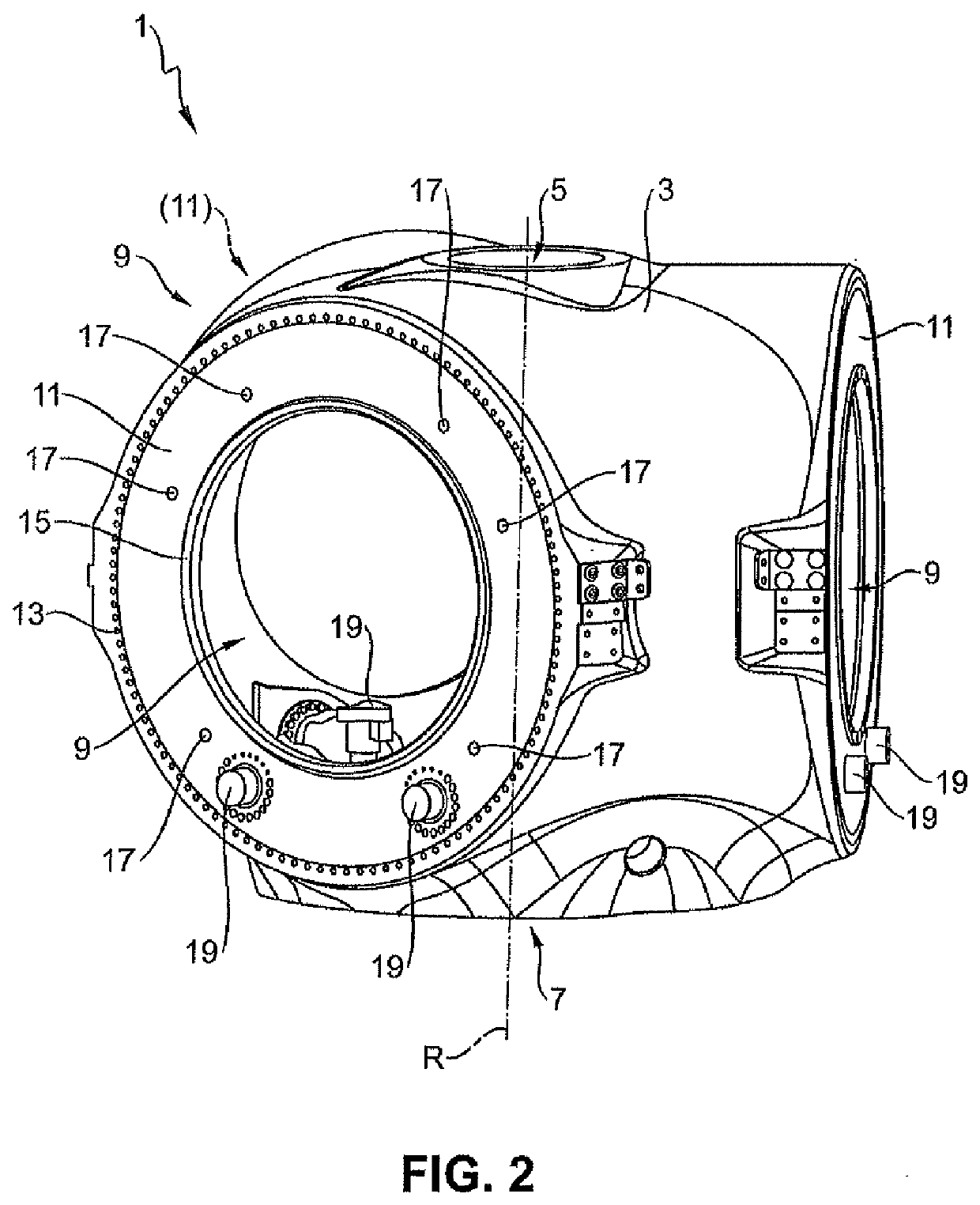
[0038]FIG. 2 shows the rotor hub 1. The rotor hub 1 has a hub housing 3. Provided in the hub housing 3 is a manhole 5 for passing therethrough towards the hub tip. The cap (not shown) of the rotor hub 1, also referred to as the spinner cap, is later accessible through the manhole 5.

[0039]Opposite the manhole 5, the rotor hub 1 has a connecting flange 7 for connecting the rotor hub 1 with a rotary connection. The rotor hub 1 can be connected in generally known manner to the rest of the nacelle 104 of the wind turbine 100.

[0040]A rotor axis R extends through the rotor hub 1 in the longitudinal directio...


PUM


Abstract

A rotor hub of a wind turbine comprising a hub housing, which has a plurality of connecting flanges, which are each adapted for connection of a rotor blade, wherein each of the rotor blades is coupled to a pitch drive for rotating the rotor blade, wherein the pitch drive is connected to an arrangement of electrical control devices, which are adapted to control the pitch drive. The arrangement of the control devices is provided in a module as a structural unit, the module being connected as a whole to the hub housing.

Description

BACKGROUNDTechnical Field[0001]The invention concerns a rotor hub of a wind turbine.Description of the Related Art[0002]On the German application from which priority is claimed the German Patent and Trade Mark Office searched the following documents: DE 102007008167 A1, DE 102010043435 A1, DE 102014200276 A1, DE 202005007450 U1 and WO2015 / 090655 A1.[0003]Wind turbines are nowadays usually equipped with rotor blades whose pitch angle relative to the wind can be altered by motor means. In that way it is possible to influence the amount of ‘mechanical’ energy taken from the wind. If the power consumption and thus also the generation of electrical power by the wind turbine is to be reduced with high wind loads or a high network load then the blade angle is altered by means of the pitch drives in such a way that less mechanical energy is taken by the blade and the speed of rotation of the rotor hub decreases. Open-loop and closed-loop control methods for altering the pitch angle are gene...

Claims


Application Information

Patent Timeline
Patent Type & Authority Applications(United States)
IPC IPC(8): F03D1/06F03D7/02F03D80/50
CPCF03D1/0658F03D7/0224F03D80/50F05B2230/60F05B2260/79F05B2260/30F03D1/0691F05B2260/74Y02E10/72
Inventor SCHMID, JONASGERDES, FRANKJANSSEN, AIKE
Owner WOBBEN PROPERTIES GMBH
Why Eureka
Try Eureka