Image-reading apparatus

a technology of image-reading apparatus and reading device, which is applied in the direction of electrical apparatus, picture communication, etc., can solve the problems of data loss, user inability to turn off the electronic device,

Active Publication Date: 2015-11-05
PFU LTD
View PDF1 Cites 3 Cited by
  • Summary
  • Abstract
  • Description
  • Claims
  • Application Information

AI Technical Summary

Benefits of technology

[0007]There are needs to read a medium to be read even under circumstances where no external power source is available. Mounting a secondary battery on a manually-fed image-reading apparatus is thought to be a solution for such needs. In the manually-fed image-reading apparatus on which the secondary battery is mounted, the secondary battery is charged by electricity supplied from the external power source, and under circumstances without electricity supply from the external power source, the manually-fed image-reading apparatus operates with electricity supplied from the secondary battery itself. When a control unit of the manually-fed image-reading apparatus hangs up or freezes, the control unit is reset by removing the secondary battery from the manually-fed image-reading apparatus and forcibly cutting the electricity supply from the external power source. However, when assuming a case where the secondary battery cannot be removed from the manually-fed image-reading apparatus, it is preferable that the control unit of the manually-fed image-reading apparatus be reset by an operation thereof made by the user. However, if the control unit is reset in a simple way, such a problem may occur that the control unit is reset during use of the manually-fed image-reading apparatus, which results in loss of data being read.

Problems solved by technology

When a control unit of an electronic device hangs up or freezes, i.e., becomes stuck so as to be immovable and does not respond to any input, a user cannot turn the electronic device off even by operating an operation unit for turning the electronic device off.
However, if the control unit is reset in a simple way, such a problem may occur that the control unit is reset during use of the manually-fed image-reading apparatus, which results in loss of data being read.

Method used


Image

  • Image-reading apparatus
  • Image-reading apparatus
  • Image-reading apparatus

Examples


embodiment

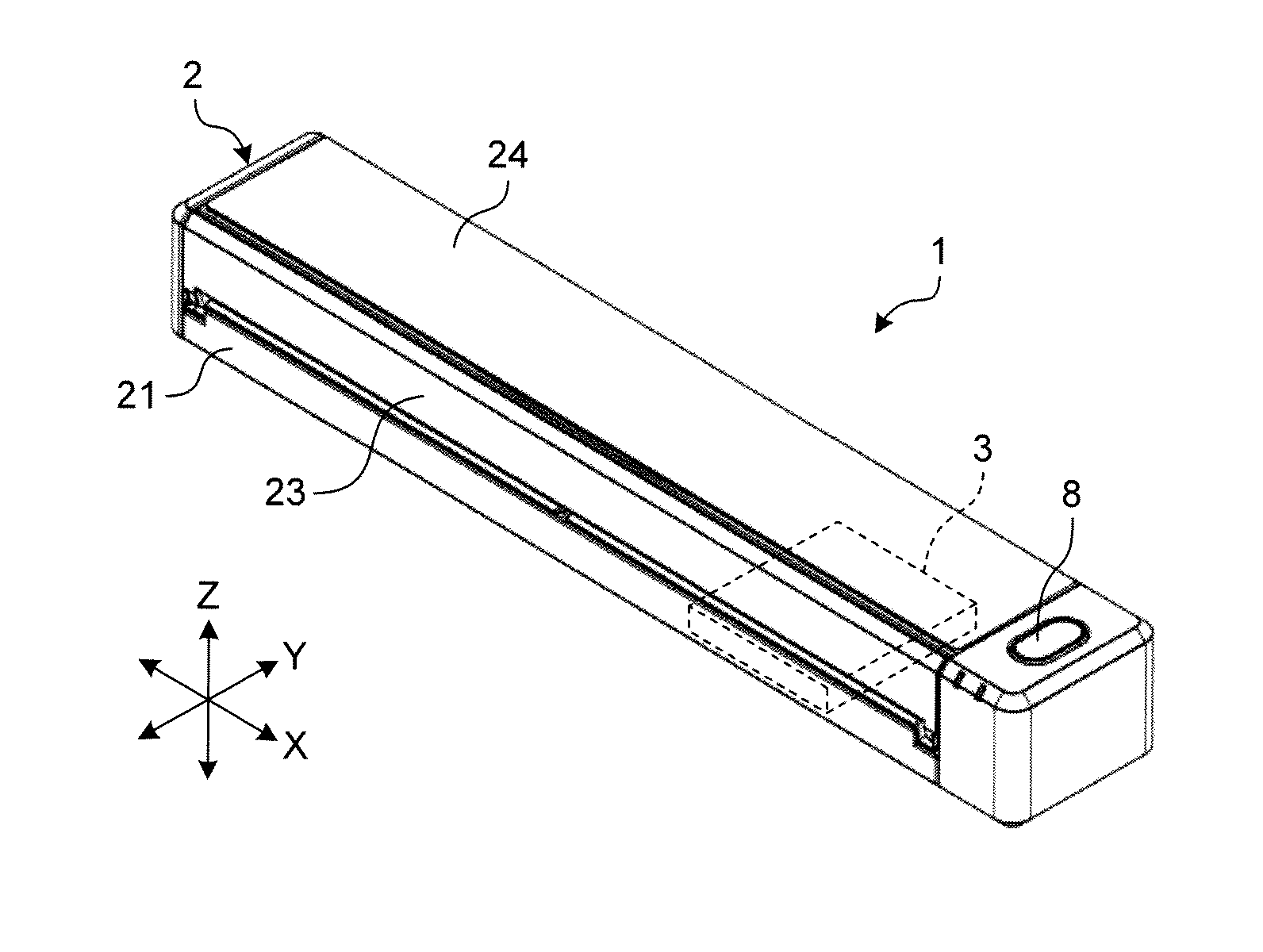
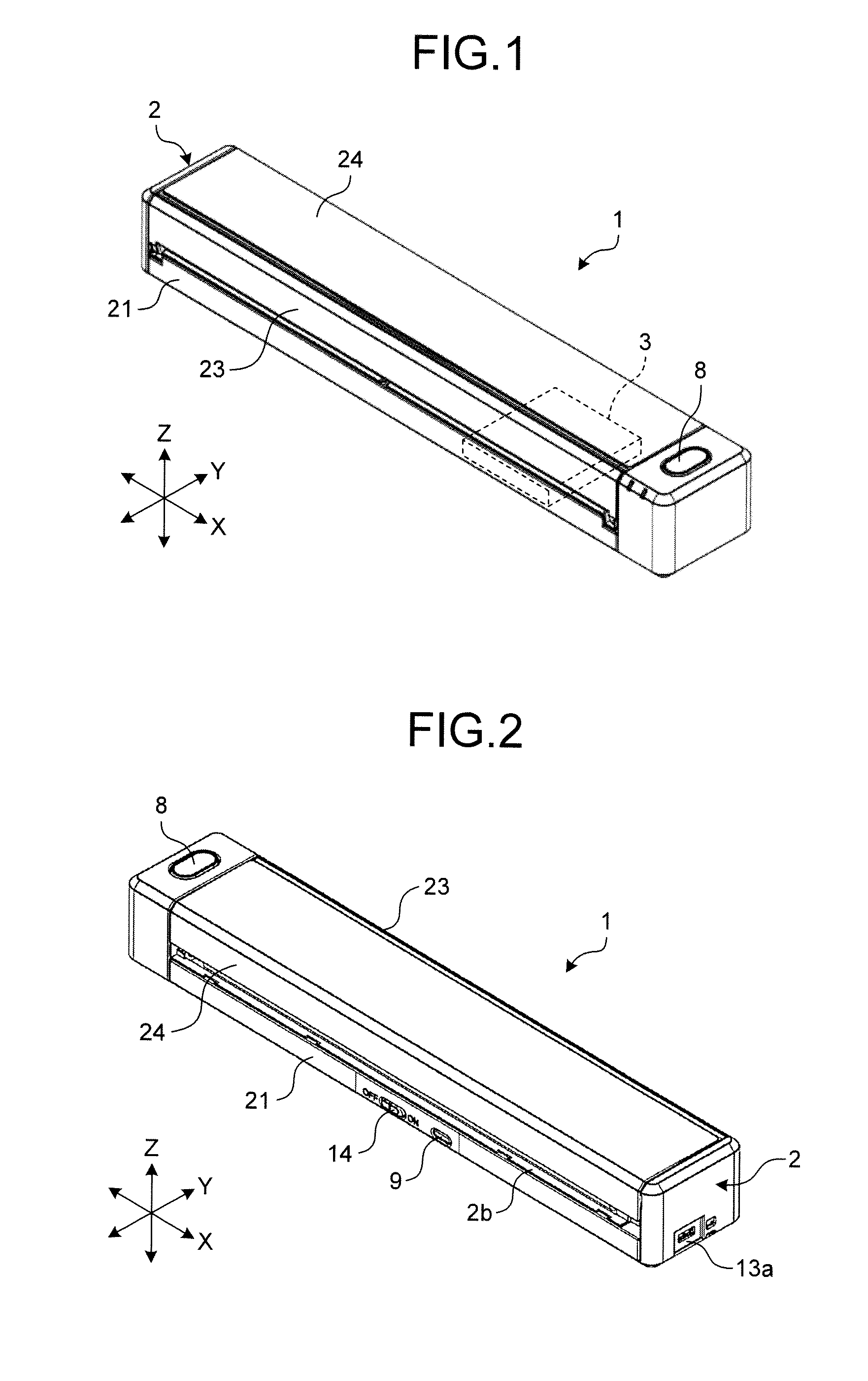
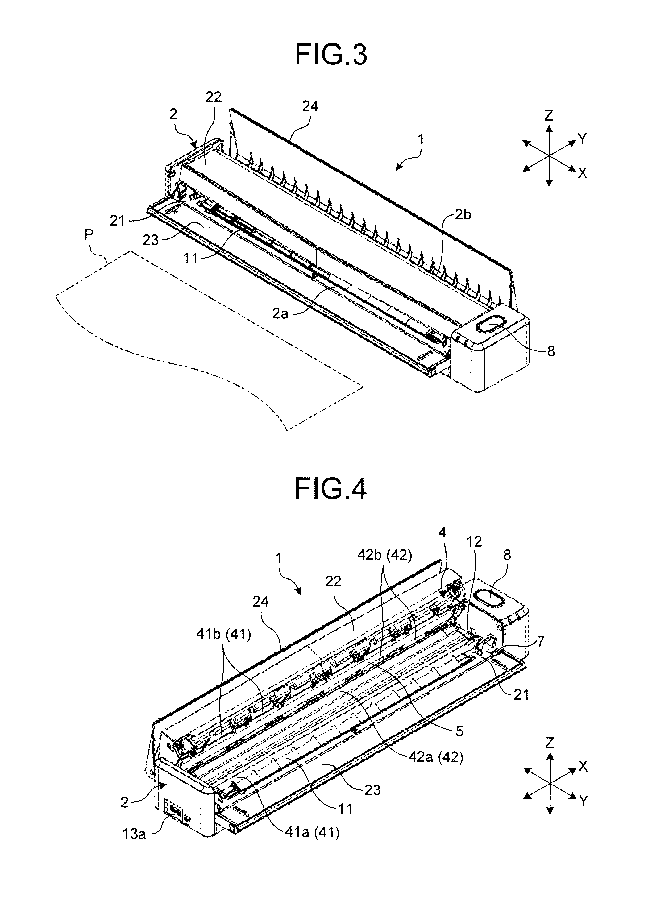
[0018]FIG. 1 is a front perspective view illustrating an image-reading apparatus according to an embodiment. FIG. 2 is a back perspective view illustrating the image-reading apparatus according to the embodiment. FIG. 3 is a perspective view of the image-reading apparatus according to the embodiment in a state of being used. FIG. 4 is a perspective view of the image-reading apparatus with its upper cover open. FIG. 5 is a block diagram of the image-reading apparatus. In FIGS. 1 to 4, the width direction of an image-reading apparatus 1 is defined as an X direction, the depth direction orthogonal to the width direction on the horizontal plane is defined as a Y direction, and the vertical direction orthogonal to the width and the depth directions is defined as a Z direction. FIG. 5 is a functional block diagram where functions of the image-reading apparatus according to the embodiment are illustrated in blocks.

[0019]As illustrated in FIG. 1, the image-reading apparatus 1 according to t...


PUM


Abstract

An image-reading apparatus includes a battery that is built-in in a housing, a conveying unit conveying a medium, an image capturing unit capturing an image of the medium, a control unit controlling at least the conveying unit and the image capturing unit, a setting-table-opened / closed sensor as a state detector detecting whether the image capturing unit is ready to read the medium, a reset unit resetting the control unit, a scanning button and a Wi-Fi protected setup (WPS) button, each of which is an operation unit disposed on an outer peripheral surface of the housing and used for giving an instruction to the control unit. The reset unit resets the control unit upon satisfaction of a first condition that the setting-table-opened / closed sensor determines that the image capturing unit is unready to read the medium and a second condition that the operation unit is operated.

Description

CROSS-REFERENCE TO RELATED APPLICATION(S)[0001]The present application claims priority to and incorporates by reference the entire contents of Japanese Patent Application No. 2014-094072 filed in Japan on Apr. 30, 2014.BACKGROUND OF THE INVENTION[0002]1. Field of the Invention[0003]The present invention relates to an image-reading apparatus.[0004]2. Description of the Related Art[0005]Examples of image-reading apparatuses include a manually-fed image-reading apparatus including an image-capturing unit and a conveying unit to convey a medium such as paper to the image-capturing unit, where a user feeds the medium to the conveying unit thereof, guiding the medium with the user's hands. Conventionally, for the sake of portability, such a manually-fed image-reading apparatus operates to read a medium using only an external power source such as a personal computer.[0006]When a control unit of an electronic device hangs up or freezes, i.e., becomes stuck so as to be immovable and does not...

Claims


Application Information

Patent Timeline
Patent Type & Authority Applications(United States)
IPC IPC(8): H04N1/00
CPCH04N1/00588H04N1/00928
Inventor KANAYA, SHINGO
Owner PFU LTD
Why Eureka
Try Eureka