Containment integrity sensor device

a sensor device and integrity technology, applied in the direction of instruments, structural/machine measurement, material strength using tensile/compressive forces, etc., can solve the problems of non-uniform material, important production loss factor, and error in compression or torque load measurement, etc., to improve the sensitivity and other characteristics of the sensor.

Inactive Publication Date: 2015-11-12
SCANIMETRICS
View PDF12 Cites 9 Cited by
  • Summary
  • Abstract
  • Description
  • Claims
  • Application Information

AI Technical Summary

Benefits of technology

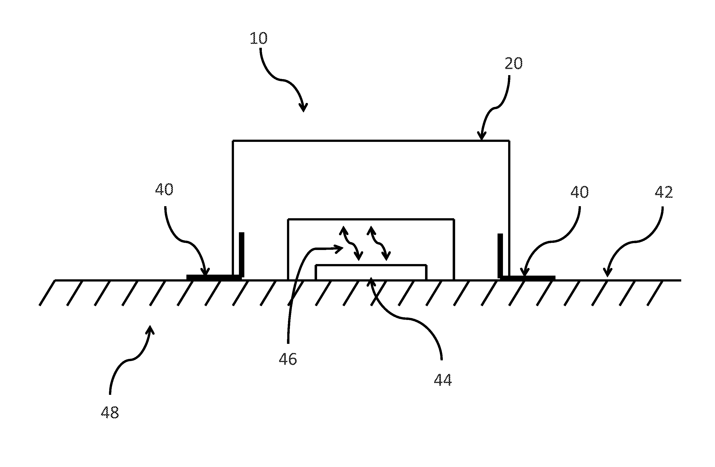
[0035]According to an aspect, there is provided a discrete gasket sensor device, comprising a force sensor integrally formed within an elastic compressible material, the elastic compressible material translates displacement a first surface relative to a second surface into a force where the force sensor generates an electrical signal that is proportional to the displacement of the elastic compressible material. The sensor may be constructed of the same or similar material as the seal or gasket. Alternatively, the sensor may be constructed of a different material as

Problems solved by technology

Another aspect of Bennett involves errors in the measurement of the compression or torque load that arise due to a non-uniform sealing material.
A non-uniform material can arise due to non-uniform density of conductive particles within the seal material and due to a non-uniform thickness of the seal material.
Equipment downtime, both scheduled and unscheduled, is an important factor of production loss.
Finding the balance between repairing often and continuing to produce is often difficult.
As an example, strain and fatigue measurements reveal risks of yield failures and cracking, changes in material properties, and remaining equipment life, making them incredibly useful for CBM if monitored.
In the infrastructure, mining and energy industries, strain and vibration are not generally monitored by built-in systems, mainly due to the complexity of sensor installation and computational intensity of the data processing.
Thermal cycles, vibration, shock, fatigue, normal force and other mechanical influences cause the gaskets to loose their seal resulting in LOC.
Unfortunately, existing CBM solutions have been historically inaccurate, are expensive or non-viable, and/or produce poor signal transmission and short battery life.
However, monitoring the hundreds of assets used every day in a civil and industrial operations requires many sensors and many more wires, which are difficult and expensive to install and maintain.
Moreover, the data requirements for continuous monitoring are large leading to large storage req

Method used


Image

  • Containment integrity sensor device
  • Containment integrity sensor device
  • Containment integrity sensor device

Examples


example 1

[0170]A pipeline integrity sensor was designed for monitoring the structural integrity of oil and slurry pipelines. In this example, the pipe wall thickness was monitored at critical locations. A Slurry Flow Loop (SFL) test facility was used for testing the pipeline integrity sensors.

[0171]Wear sensors were used for the pipe thickness measurement. The sensors were installed to critical locations on an 8″ diameter carbon steel test spool at the SFL. The data was collected using wireless sensing devices provided by Scanimetrics Inc. For assessment of the specific sensors results were compared using standard methods, such as ultrasonic thickness measurement and calipers to measure parameters for validation of the wireless sensor outputs.

[0172]An initial site survey was performed to verify cellular connectivity at the SFL. The installation of the pipeline integrity sensors included 6 wear sensors for the pipe thickness measurement, 8 stud tension sensors and 8 flange gap sensors for pip...

example 2

[0175]Pipeline integrity sensors were designed for monitoring the structural integrity of oil and slurry pipelines. In this example the flange integrity was monitored at critical locations. A Pilot-Scale Slurry Flow Loop (SFL) facility was used for testing the pipeline integrity sensors.

[0176]Wear sensors were used for the pipe thickness measurement. The sensors were installed at critical locations on an 8″ diameter carbon steel test spool at the SFL facility. The data was collected using wireless sensing devices from Scanimetrics Inc. For assessment of the specific sensors, the results were compared using standard methods, such as digital torque gages and calipers, and ultrasonic tension measurement were used to manually measure parameters for validation of the wireless sensor outputs.

Pilot Integrity Sensor

example 3

[0177]Pipeline integrity sensors were used for monitoring the structural integrity of oil and slurry pipelines. In this example, pipe wall thickness of a multi layer pipe was monitored, such as a Chromium Carbide Overlay pipe, Urethane Lined pipe, Rubber pipe and Rubber Lined pipe. In each case the sensor probe length was designed such that the distal end of the probe aligned with the wear surface at the time the sensor was installed.

[0178]Alternatively, the length of the probe could have been designed such that the distal end of the probe extended beyond the wear surface providing an way to calibrate the sensor for relative position due to insertion position errors, thread errors, etc. In another embodiment, the length of the probe could have been designed such that the distal end of the probe remained below the wear surface by 0.5 mm, 1.0 mm, 1.5 mm, 2.0 mm or more. Such a configuration would not actuate until the wear reached the distal end of the probe as described earlier.

[0179...


PUM


Abstract

A containment integrity sensor device has a force sensor integrally formed within an elastic compressible material, the elastic compressible material having a first surface and a second surface opposite the first surface. The force sensor generates a signal in response to a compressive force applied to the first and second surfaces, the signal being indicative of the compressive force.

Description

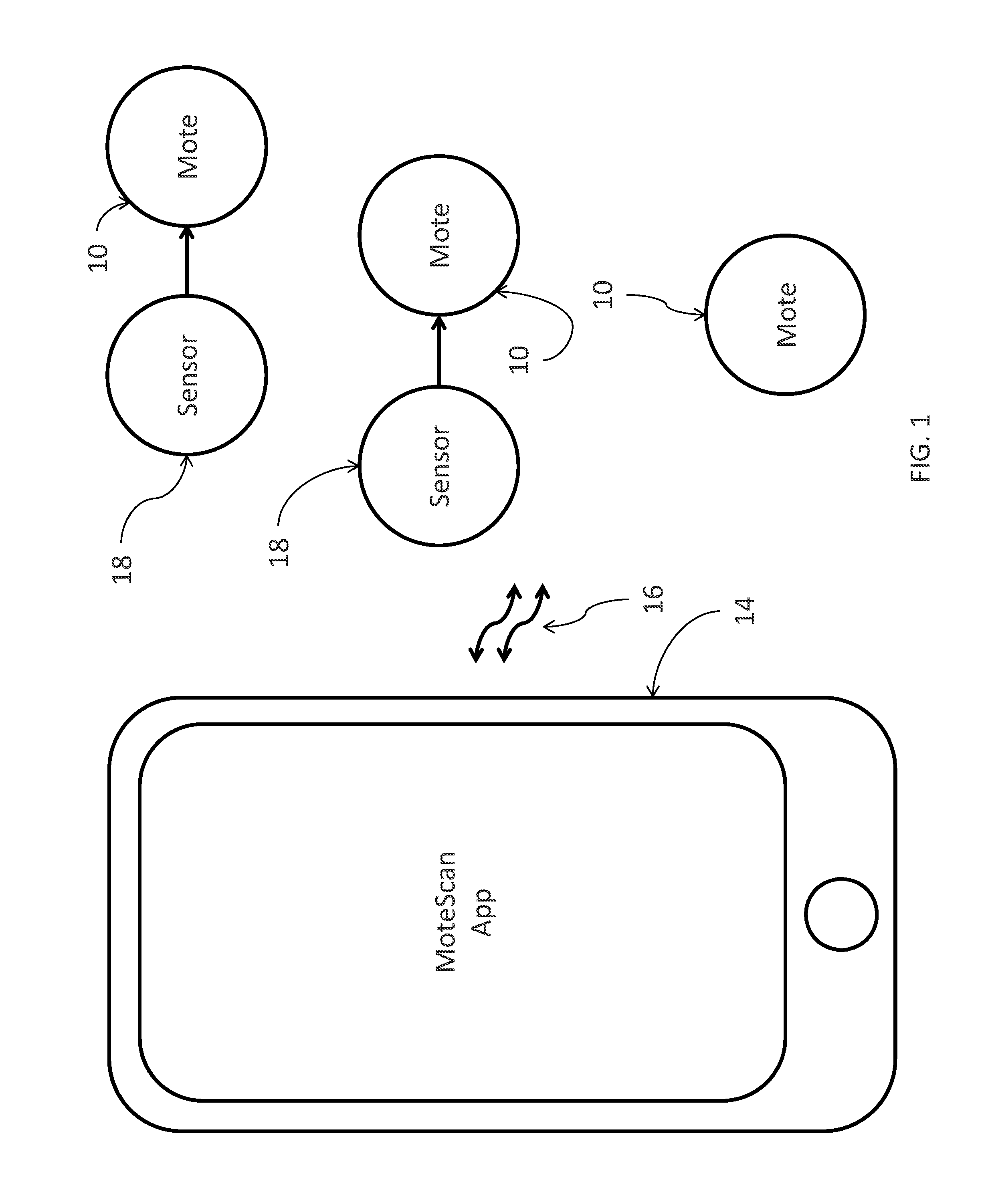
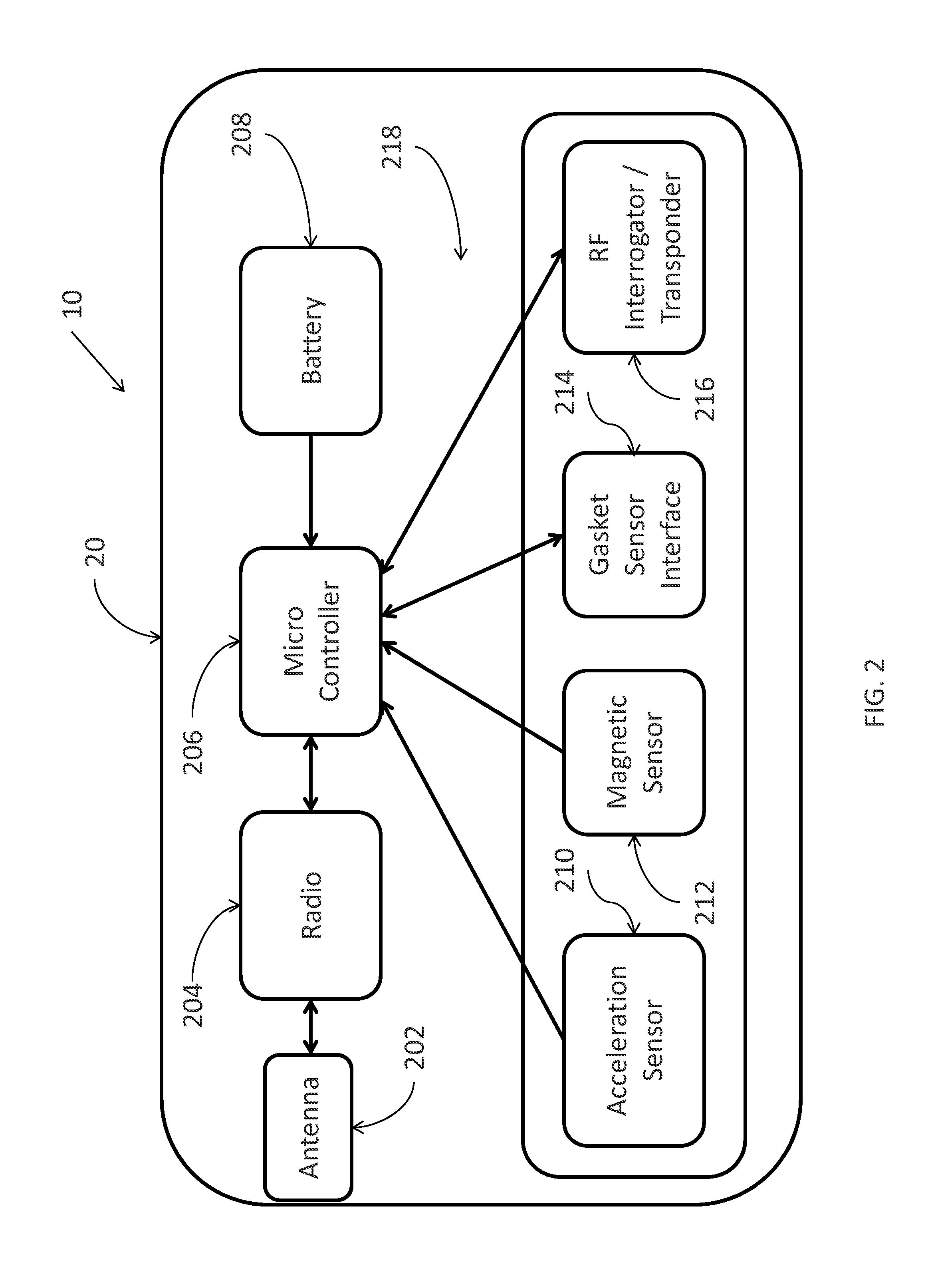
FIELD[0001]This relates to a containment integrity sensor device, which may be referred to as a gasket sensor, a wear sensor or a combination thereof herein. In particular, the wear sensor may be a compressible elastic displacement sensor or wear sensor, to be attached to a component of equipment or a structure for determining status and sensing one or more changes occurring at that component, such as alignment, gap, unloading, creep, wear, disintegration and failure. The sensor is sealed so that it may be operated in either hazardous or non-hazardous environments and is compatible with liquids, temperature, vibration and other environmental conditions.BACKGROUND[0002]Sensors are used to determine and monitor status and conditions of equipment and the environment at that equipment. For example, a sensor may be used to monitor temperature, humidity, atmosphere at an environment or other ambient conditions. Other sensors are used to monitor physical parameters of equipment, and the st...

Claims


Application Information

Patent Timeline
IPC IPC(8): G01N3/08G01M99/00
CPCG01M99/007G01N3/08G01M5/0033G01M13/005
Inventor SLUPSKY, STEVENSELLATHAMBY, CHRISTOPHER
Owner SCANIMETRICS
Why Eureka
Try Eureka