Lock device having position sensor

a technology of position sensing and lock device, which is applied in the direction of burglar alarm mechanical actuation, instruments, stray field compensation, etc., can solve the problems of increasing manufacturing and/or installation time and costs, and unauthorized attempts to circumvent the monitoring of the reed switch

Active Publication Date: 2015-11-19
SCHLAGE LOCK
View PDF11 Cites 50 Cited by
  • Summary
  • Abstract
  • Description
  • Claims
  • Application Information

AI Technical Summary

Problems solved by technology

However, such security devices often require addition preparation and permanent modification of the door and door frame, such as, for example, modification necessary for the secured placement of the magnet and reed switch in/to the door or door frame.
Such additional preparation and modification can increase manufacturing and/or

Method used


Image

  • Lock device having position sensor
  • Lock device having position sensor
  • Lock device having position sensor

Examples


Embodiment Construction

[0013]For the purposes of promoting an understanding of the principles of the invention, reference will now be made to the embodiments illustrated in the drawings and specific language will be used to describe the same. It will nevertheless be understood that no limitation of the scope of the invention is thereby intended, any alterations and further modifications in the illustrated embodiments, and any further applications of the principles of the invention as illustrated therein as would normally occur to one skilled in the art to which the invention relates are contemplated herein.

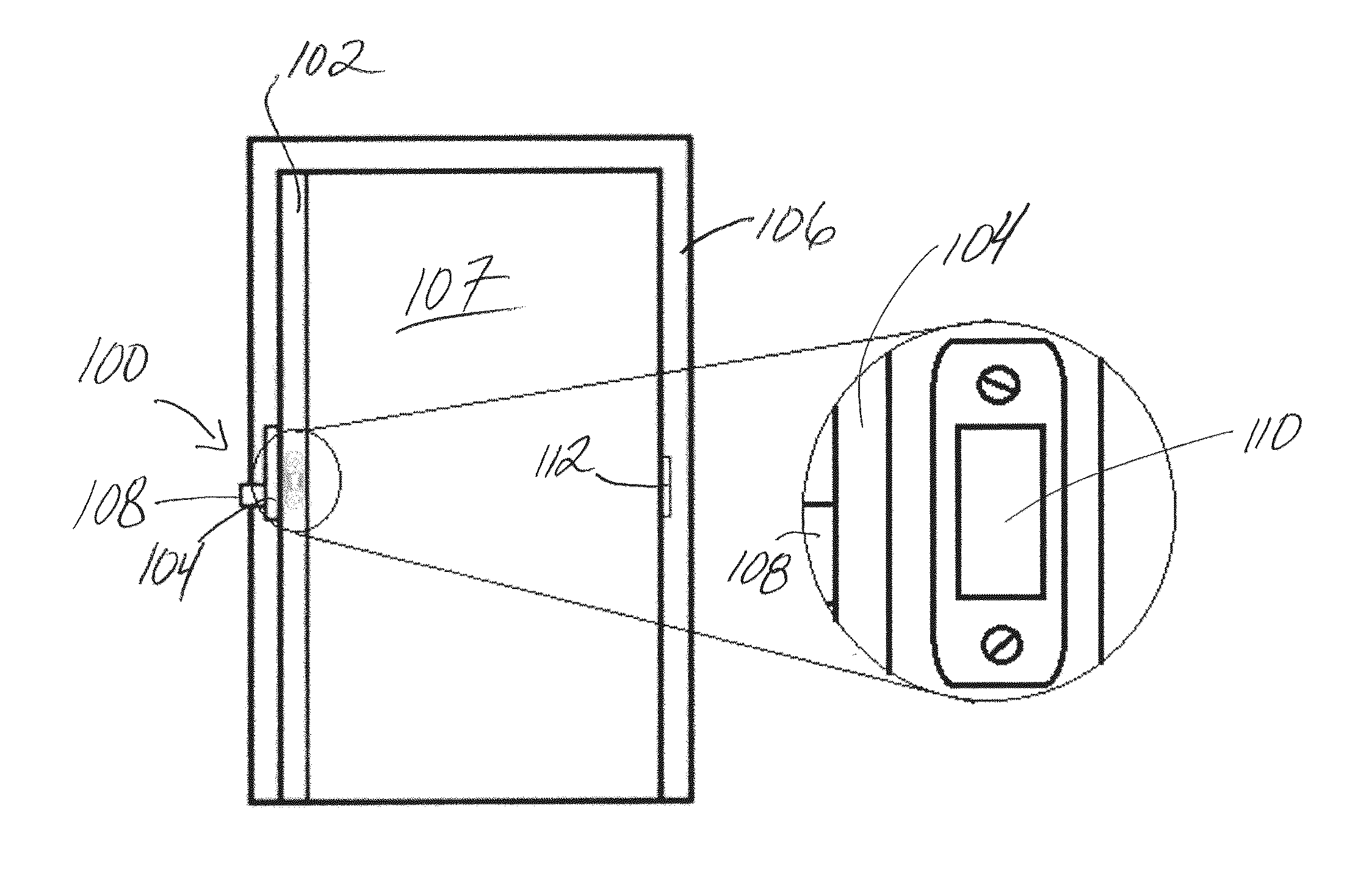
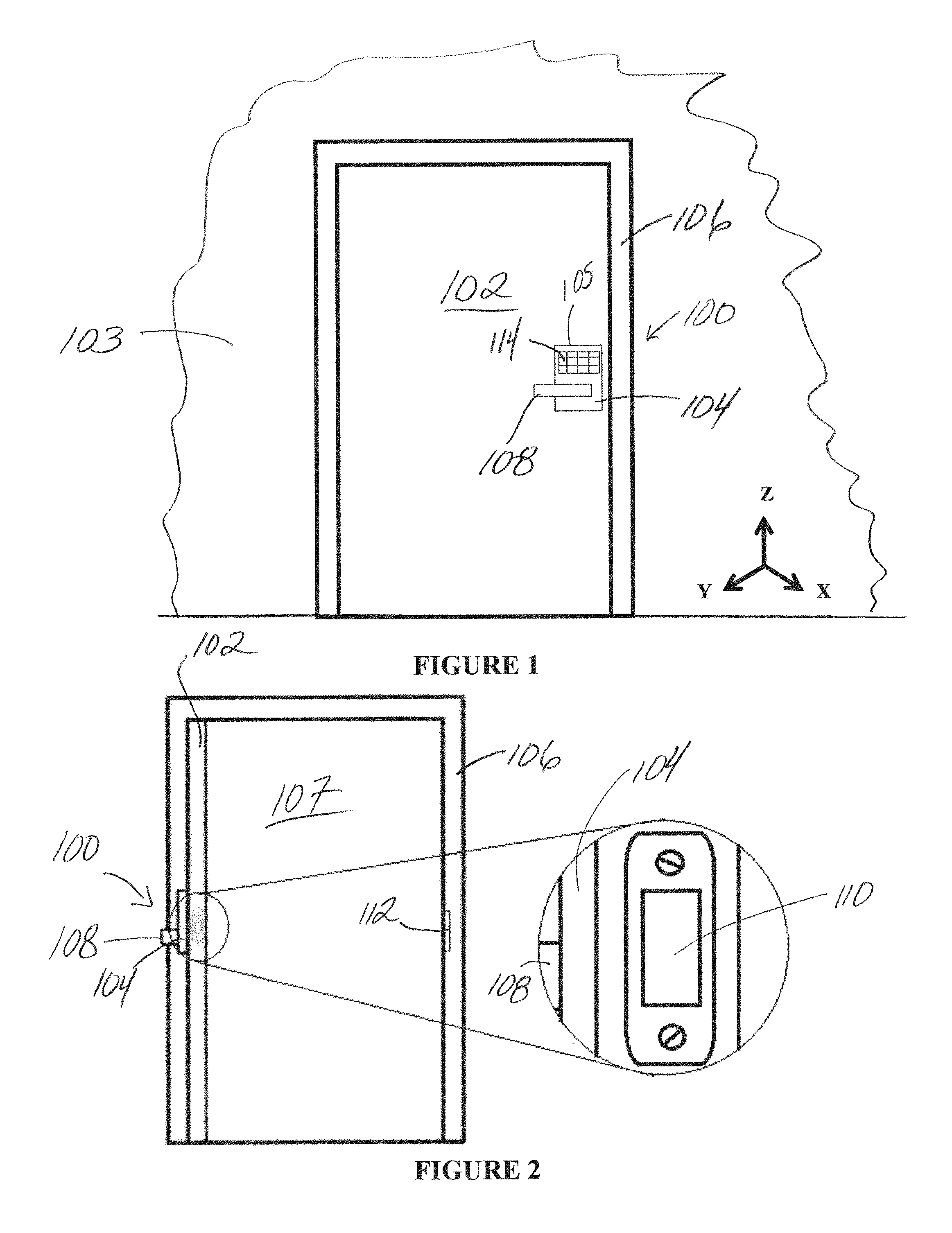
[0014]FIGS. 1 and 2 illustrate a position sensing system 100 used with a door 102 that may be moved between closed and open positions, and which includes a lock device 104 having position sensing capabilities according to an illustrated embodiment of the present invention. According to certain embodiments, the door 102 is operably mounted to a door frame 106 or to an adjacent structure or wall 103, such...


PUM


Abstract

A position sensing system and method for detecting the displacement of a door from a reference position, such as, for example, from a closed position. The system includes a magnetometer that may be operably connected to the door, and which measures positional location relative to a reference magnetic field, such as, for example, a magnetic field provided by a magnet of a lock device. The system may also include an accelerometer that detects acceleration of the door, and thereby provides an indication of when location is to be measured by the magnetometer. Measurement information from the magnetometer is used to derive a position indicator that is compared to a reference indicator, the reference indicator being associated with the reference position. Differences between the position and reference indicators may provide an indication that the door has been moved from the reference position.

Description

CROSS REFERENCE TO RELATED APPLICATIONS[0001]The present application claims the benefit of U.S. Provisional Patent Application No. 61 / 992,698, filed on May 13, 2014, which is hereby incorporated by reference in its entirety.BACKGROUND[0002]Embodiments of the present invention generally relate to lock devices having position sensing capabilities. More particularly, embodiments of the present invention relate to lock devices having a magnetometer for detection of a position of a door.[0003]Security systems can monitor the position of a door, gate, panel, or other similar access barrier (collectively referred to herein as “doors”) relative to an associated entryway or structure. Such positional information may provide an indication as to whether the door is positioned to prohibit or allow ingress or egress into / from the associated entryway and / or structure. Certain types of monitoring systems use a reed switch and magnet, wherein the reed switch is altered between open and closed posit...

Claims


Application Information

Patent Timeline
IPC IPC(8): E06B7/28G01B7/14
CPCG01B7/14E06B7/28G08B13/08G08B29/181
Inventor KINCAID, RYAN C.FOCKE, GABRIEL D.TELLJOHANN, BRIAN A.RETTIG, RAYMOND F.DEXTER, MATTHEWRAYBURN, RYNE
Owner SCHLAGE LOCK
Why Eureka
Try Eureka