Thread Cleaning Apparatus Having Adjustable Diameter Brush Bases

Active Publication Date: 2015-11-26
SUBARU TECNICA INTERNATIONAL
View PDF0 Cites 58 Cited by
  • Summary
  • Abstract
  • Description
  • Claims
  • Application Information

AI Technical Summary

Problems solved by technology

Although apparatus with adjustable brush carrier diameters have been made, various limitations exist as to known designs.
In summary, the known prior

Method used


Image

  • Thread Cleaning Apparatus Having Adjustable Diameter Brush Bases
  • Thread Cleaning Apparatus Having Adjustable Diameter Brush Bases
  • Thread Cleaning Apparatus Having Adjustable Diameter Brush Bases

Examples


Embodiment Construction

)

[0016]While various designs of tubular thread cleaning apparatus can embody the principles of the present invention, with reference to the drawings some of the presently preferred embodiments can be described.

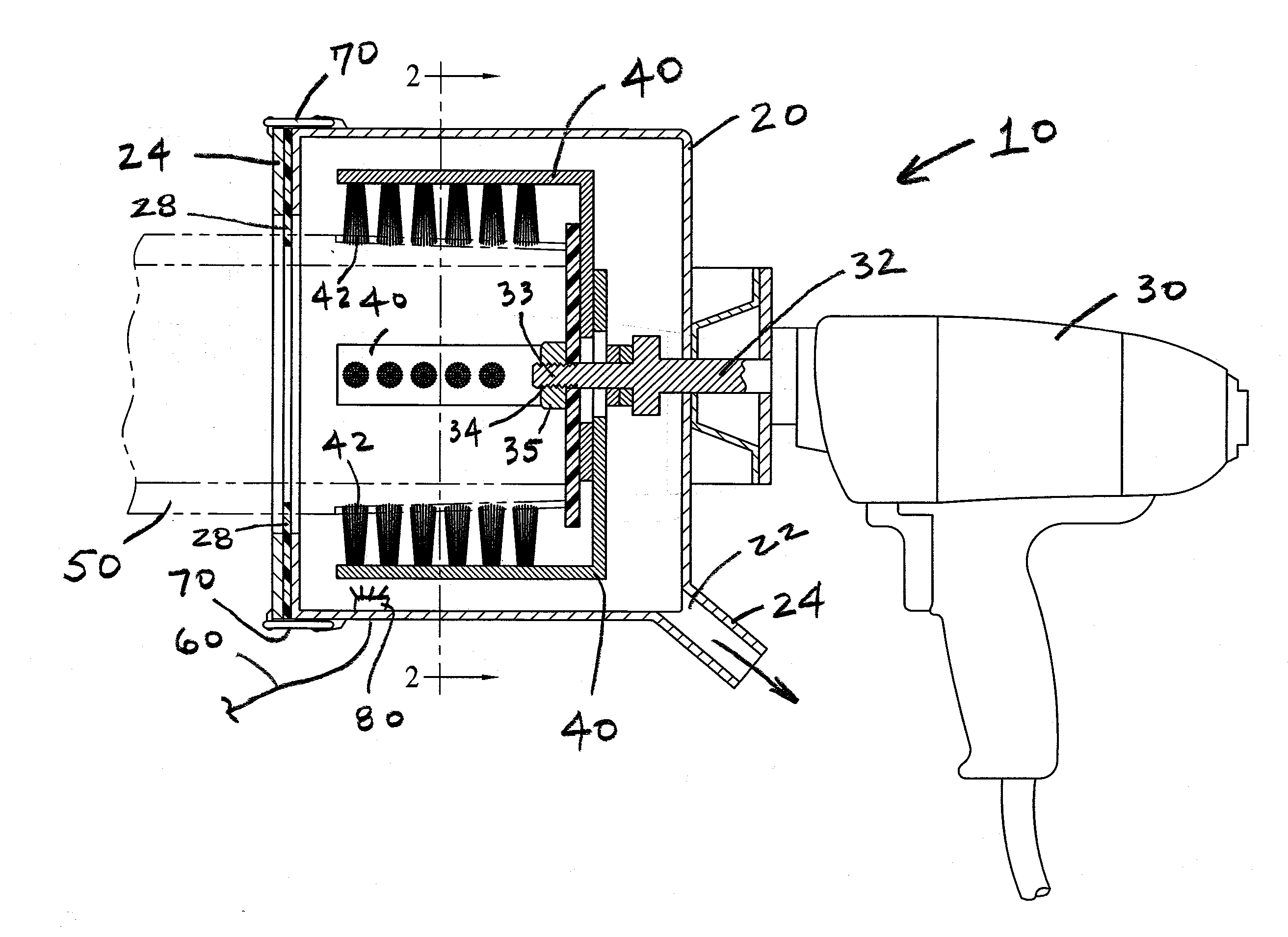
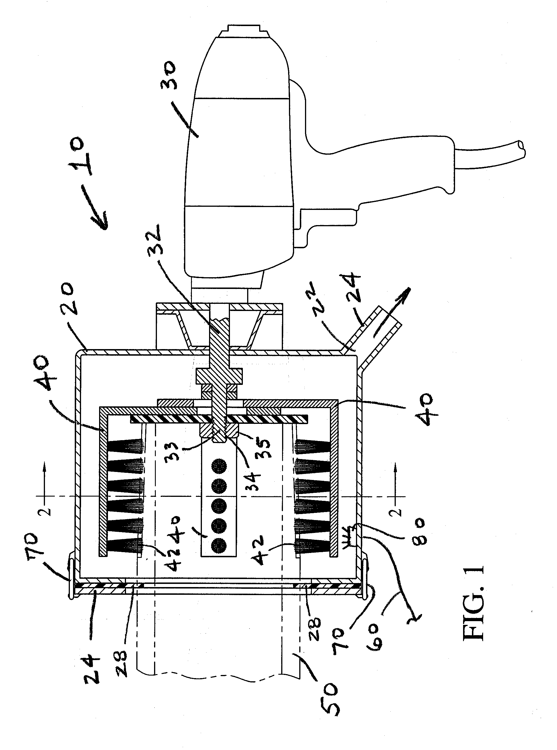
[0017]FIG. 1 is a side view in partial cross section of the thread cleaning apparatus 10. A drum 20 is attached to rotary driver 30. Rotary driver 30 may be a common hand-held electric motor driven unit, similar to a common electric drill. Alternatively, rotary driver 30 may employ hydraulic or pneumatic motors to generate rotation. Shaft 32 is the rotating member driven by rotary driver. Shaft 32 comprises an extended section 33, over which the brush brackets fit (described below), and the distal end of shaft 32 preferably comprises threads 34, on which nut 35 can be screwed.

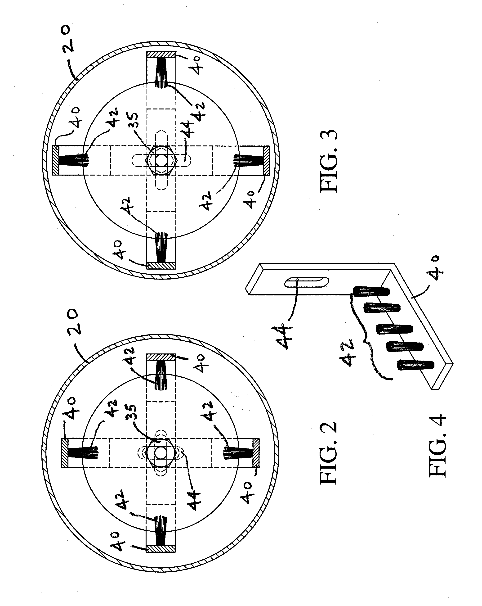
[0018]Referring to FIG. 1, and in more detail to FIGS. 2-4, thread cleaner 10 comprises a plurality of brush brackets 40, on which are mounted brushes 42 which engage the threads of a tubular 50. The embo...


PUM

PropertyMeasurementUnit
Flow rateaaaaaaaaaa
Diameteraaaaaaaaaa

Abstract

An apparatus for cleaning of tubular threads having adjustable spacing brushes to accommodate tubulars of different diameters. A plurality of brushes are rotated in a drum, which fits over the tubular connection. The brushes are mounted on L-shaped brackets, which are in turn mounted to a rotary driver by a shaft extending through slots in the brackets. By loosening the attachment of the brackets on the rotary driver, the brackets can be slid radially inward or outward to the extent of the slots, thereby adjusting the diameter of the threads that can be cleaned. The front access plate and seal plate, through which the tubular extends into the drum, are preferably held to the drum by hand operable latches. Solvent may be injected into the drum and onto the threads by a hand pump, and captured in the drum and drained into a container for disposal or reuse.

Description

CROSS REFERENCE TO RELATED APPLICATIONS[0001]Not applicable.BACKGROUND[0002]Field of the Invention[0003]This invention relates to apparatus for cleaning of threads on tubular goods.[0004]Tubular goods with threads on either ends are commonly used in many industries. As an example, tubular goods such as drill pipe, tubing, and casing are used in connection with drilling and completion of oil and gas wells in the petroleum industry.[0005]Various compounds, typically a thick paste type product, are frequently applied to the threads on the tubular goods, to serve friction reducing, sealing, and other functions. Certain of such compounds are commonly referred to as “pipe dope.” When tubulars, for example drill pipe, are removed from a well, it may be necessary to inspect the threads to ensure that they are suitable for re-use (i.e. no cracks, galling, etc.). It can be appreciated that in order to accomplish a proper inspection it is necessary for the thread surface to be cleaned of pipe ...

Claims


Application Information

Patent Timeline
IPC IPC(8): A46B13/04B08B1/00
CPCB08B1/002A46B13/04B08B1/04B08B9/021E21B17/006A46B13/02A46B2200/3013B08B9/023B08B9/027B23G9/009B23G2200/20
Inventor EDMOND, ANTHONY JOHNHARPER, RYANSTELLY, DAVID
Owner SUBARU TECNICA INTERNATIONAL
Why Eureka
Try Eureka