Backlight assembly and display apparatus

a backlight assembly and display device technology, applied in the field of display technology, can solve the problems of uneven connection between the film member and the support plate, scratches on the support plate, and wrinkles in the film member

Active Publication Date: 2015-11-26
BOE TECH GRP CO LTD +1
View PDF14 Cites 0 Cited by
  • Summary
  • Abstract
  • Description
  • Claims
  • Application Information

AI Technical Summary

Benefits of technology

[0007]Embodiments of the present invention provide a backlight assembly capable of preventing a film member from dropping off the support plate.

Problems solved by technology

However, with the structure mentioned above, the positioning notch and the corresponding positioning protrusion of the film member and the support plate match each other just right without sufficient gap left between the positioning protrusion and the positioning notch.
In this case, when performing temperature and humidity test on the backlight assembly in a later process, the expansion and retraction of the film member will be restricted resulting in wrinkles in the film member.
Further, in the structures mentioned above, the connection between the film member and the support plate are not firm.
Therefore, when performing vibration test on the backlight assembly later, the film member tends to drop off the support plate, thus, scratches may be formed on the support plate, or the film member may be pressed by a glue frame in the backlight assembly.

Method used


Image

  • Backlight assembly and display apparatus
  • Backlight assembly and display apparatus
  • Backlight assembly and display apparatus

Examples


Embodiment Construction

[0023]Exemplary embodiments of the present invention will be described hereinafter in detail with reference to the attached drawings, wherein the like reference numerals refer to the like elements. The present invention may, however, be embodied in many different forms and should not be construed as being limited to the embodiment set forth herein; rather, these embodiments are provided so that the present invention will be thoroughly and completely understood.

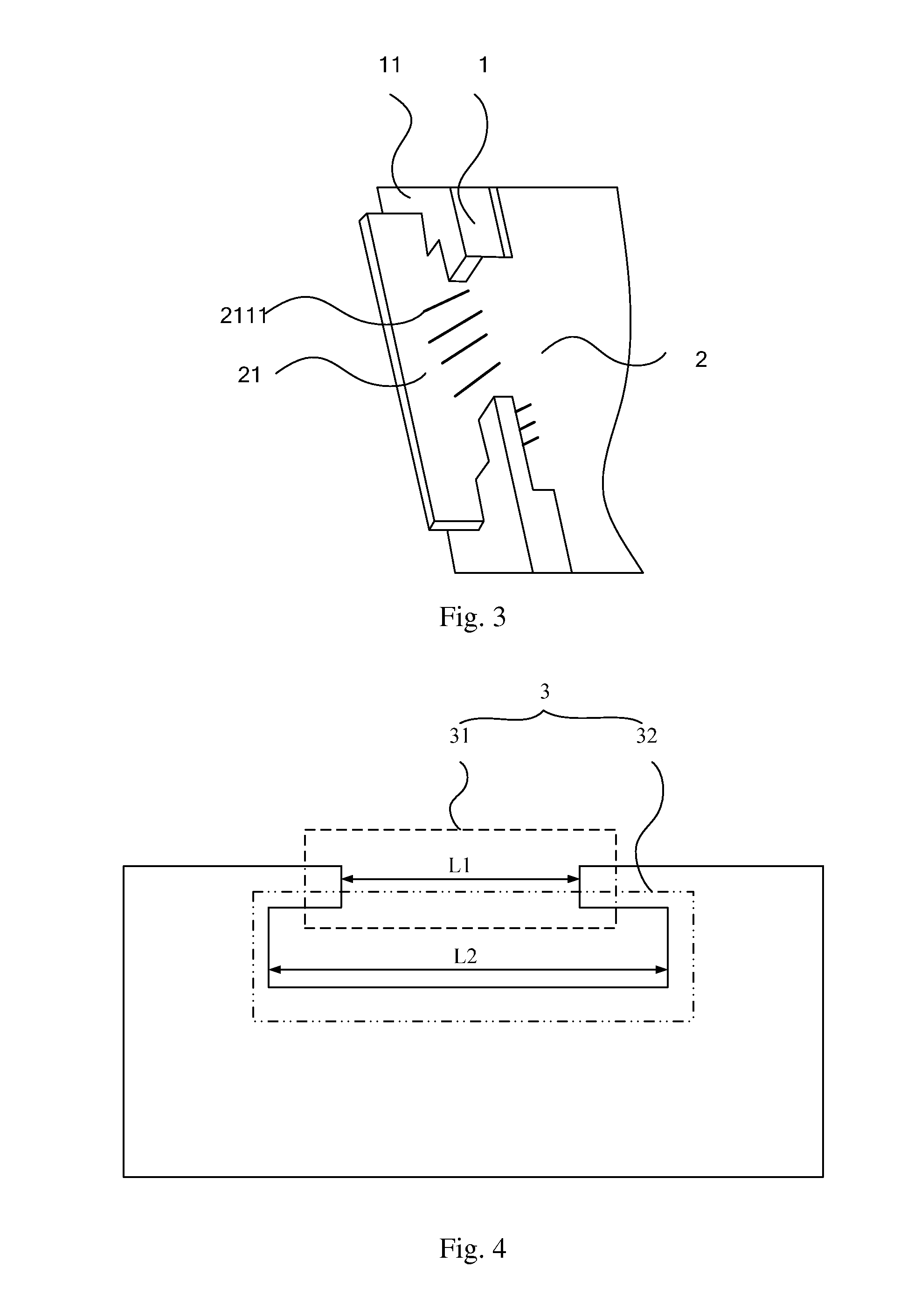
[0024]FIG. 3 is a partial structural view showing a backlight assembly according to an exemplary embodiment of the present invention. As shown in FIG. 3, the backlight assembly comprises a film member 2 and a support frame 1. The support frame 1 comprises a bottom plate (not shown) and four side plates 11 (just shown one). The bottom plate and the four side plates define a recess for receiving the film member. At least one side plate 11 is formed with a stepped notch 3 (referring to FIG. 4).

[0025]FIG. 4 is a schematic structur...


PUM

PropertyMeasurementUnit
widthaaaaaaaaaa
thicknessaaaaaaaaaa
sizeaaaaaaaaaa

Abstract

Disclosed are a backlight assembly and a display apparatus comprising the backlight assembly. The backlight assembly comprising: a film member; and a support frame holding the film member; the support frame comprising at least one support plate; the support plate is provided with a stepped notch including a first notch and a second notch extending from the first notch and open to an edge of the support plate and having a width smaller than the first notch; the film member is provided with a protrusion for engaging with the stepped notch, the protrusion including a first part projecting from the film member and a second part extending from the first part and having a width larger than the first part; wherein the width of the second part of the protrusion is larger than that of the first notch of the stepped notch, and the width of the second notch of the stepped notch is smaller than that of the first part of the protrusion, such that when the protrusion is engaged with the stepped notch, the first part of the protrusion engages the first notch of the stepped notch, with the second part of the protrusion positioned outside the support plate for restraining the film member in an extending direction of the film member; and the second notch of the stepped notch is positioned over the first part of the protrusion for restraining the film member in a height direction of the support plate. The backlight assembly with the above structure can prevent the film member from dropping off the support plate.

Description

CROSS-REFERENCE TO RELATED APPLICATION[0001]This application claims the benefit of Chinese Patent Application No. 201410225261.3 filed on May 26, 2014 in the State Intellectual Property Office of China, the whole disclosure of which is incorporated herein by reference.BACKGROUND OF THE INVENTION[0002]1. Technical Field[0003]Embodiments of the present invention relate to the field of display technology, and in particular, to a backlight assembly and a display apparatus using the backlight assembly.[0004]2. Description of the Related Art[0005]In a conventional backlight source of medium or small size, typically, a film member is secured to a support plate by providing at least a pair of protrusion and notch between the film member and the support plate and engaging the protrusion and the notch with each other. FIG. 1 shows a partial structural view of a backlight assembly in the prior art. As shown in FIG. 1, a film member positioning notch 011 is formed in a film member 01, and a sup...

Claims


Application Information

Patent Timeline
Patent Type & Authority Applications(United States)
IPC IPC(8): G02F1/01
CPCG02F1/0102G02F1/133606G02F1/133608G02F2201/465
Inventor GAI, XINWANG, NING
Owner BOE TECH GRP CO LTD
Why Eureka
Try Eureka