Vehicle comprising a viewing system and method for adjusting position of a monitor of the viewing system

a viewing system and monitor technology, applied in the direction of television systems, machine supports, transportation and packaging, etc., can solve the problems of reducing the lifetime of the monitor or at least of the support, affecting the visibility of the image, and the monitor is subject to vibrations

Pending Publication Date: 2022-06-02
VOLVO LASTVAGNAR AB
View PDF4 Cites 0 Cited by
  • Summary
  • Abstract
  • Description
  • Claims
  • Application Information

AI Technical Summary

Benefits of technology

[0017]Hence, through the imparted load, the locking device presents a suitable rigidity that enables vibrations to be absorbed. Premature deterioration of the support and the monitor can be avoided and visibility of the image displayed on the monitor is no longer affected by vibrations. Load on the movable support part can be released only in clearly identified situations, possibly decided by the driver, to adjust the position of the monitor.

Problems solved by technology

However, the monitor is subjected to vibrations which not only affect the visibility of the image but also reduces lifetime of the monitor or at least of the support.

Method used


Image

  • Vehicle comprising a viewing system and method for adjusting position of a monitor of the viewing system
  • Vehicle comprising a viewing system and method for adjusting position of a monitor of the viewing system
  • Vehicle comprising a viewing system and method for adjusting position of a monitor of the viewing system

Examples


first embodiment

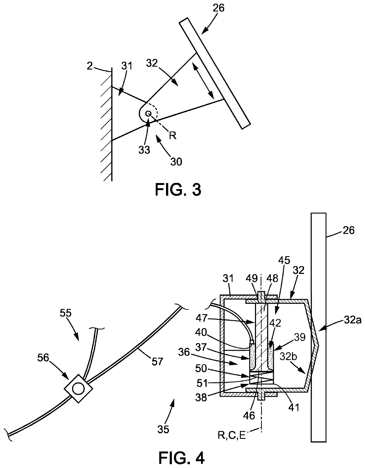
[0067]In particular, in the first embodiment, a pivot 33 extending along the transverse direction T connects the movable support part 32 to the fixed support part 31. The movable support part 32 is then movable in rotation about a rotation axis R parallel to the transverse direction T with respect to the fixed support part 31. The movable support part 32 is movable along a rotational displacement direction around the rotation axis R so that a vertical inclination of the monitor 26 can be adjusted.

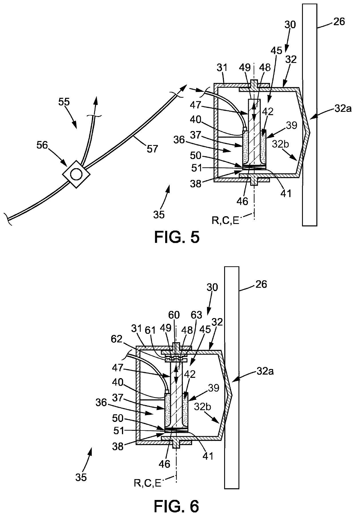
[0068]The vehicle 1 comprises a biasing system 35 presenting a locked state in which the movable support part 32 is maintained in one of the positions with respect to the fixed support part 31, and an unlocked state in which the movable support part 32 is movable with respect to the fixed support part 31.

[0069]In FIGS. 4 and 5, the biasing system 35 comprises a locking device 36 mounted on the fixed support part 31.

[0070]The locking device 36 includes a cylinder 37 having a housing 38 exten...

second embodiment

[0091]In this respect, as can be seen in FIGS. 11 to 13, in a second embodiment, the fixed 31′ and movable 32′ support parts of the support 30′ have respective spherical contact surfaces configured to slide against each other in the unlocked state of the biasing system 35′. Both vertical and horizontal inclination of the movable support part 32′ with respect to the fixed support part 31′ may be adjusted.

[0092]In this embodiment, the cylinder 37 of the locking device 36′ is arranged substantially along the longitudinal direction L with the second end wall bearing the abutment surface 41 at proximity of the contact surface of the fixed support part 31′. The locking member 45′ is configured so that the free end 49′ of the contact member 47′ protrudes through the second end wall of the cylinder 37, on a side of the abutment surface 41.

[0093]The movable support part 32′ has a trough-hole 34 extending between the back 32b′ and front 32a′ surfaces. The locking device 36′ comprises a fricti...


PUM


Abstract

A vehicle comprising a viewing system including at least one camera, a monitor and a support, the support comprising a movable support part supporting the monitor and movably mounted on a fixed support part secured to a frame of the vehicle, a biasing system comprising a locking device mounted on the fixed support part and configured to impart a load to the movable support part so as to maintain the movable support part in a position with respect to the fixed support part, and a pneumatic releasing device configured to inject compressed air in the locking device to release the movable support part from the load.

Description

FIELD OF THE DISCLOSURE[0001]The invention relates to a vehicle comprising a viewing system and to a method for adjusting position of a monitor of the viewing system.BACKGROUND OF THE DISCLOSURE[0002]A viewing system is used in a vehicle to provide a driver installed at a driving place of a compartment of the vehicle with one or several views of surroundings of the vehicle.[0003]Viewing systems have long implemented mirrors to provide the views.[0004]Mirrors in viewing systems are progressively replaced by cameras connected to a monitor so that the same views can be provided in a more accurate manner and with a better modularity thanks to the ability of processing images of the views upon acquisition by the cameras and / or display by the monitor.[0005]The monitor is arranged within the compartment of the vehicle through a support part comprising a fixed support part secured to a frame of the vehicle, and a movable support part supporting the monitor. The movable support part is movab...

Claims


Application Information

Patent Timeline
Patent Type & Authority Applications(United States)
IPC IPC(8): H04N7/18B60R1/22B60R11/02H04N5/225
CPCH04N7/183B60R1/22B60R2011/0022H04N5/225251B60R11/0235B60R11/00B60R11/0229B60R2011/0085B60R2011/0089F16P3/14F16M2200/022F16M11/06B60R2300/8046B62D1/18H04N23/531
Inventor BERNE, NICOLASDURAN, SÉBASTIEN
Owner VOLVO LASTVAGNAR AB
Why Eureka
Try Eureka