
Faucet Water Output Structure

a faucet and output structure technology, applied in mechanical equipment, transportation and packaging, valve types, etc., can solve the problems of design and performance of a faucet that are not quite satisfactory, and achieve the effect of saving and convenience for users

Inactive Publication Date: 2015-12-03
XIAMEN RUNNER IND CORP
View PDF1 Cites 1 Cited by
  • Summary
  • Abstract
  • Description
  • Claims
  • Application Information

AI Technical Summary

Benefits of technology

The present invention aims to provide a faucet water output structure that can be installed on both an over-table basin and an under-table basin through simple switching. The faucet can be manufactured in a fast and convenient manner and can be used for two different types of usage, which increases product application capability and raises market competitiveness. Additionally, the faucet can be installed in different ways to provide savings and convenience to the user.

Problems solved by technology

In this respect, the two kinds of faucets can not be used in an interchangeable manner, for that could result in unfit installation or improper installation to cause aesthetical problems.
Therefore, presently, the design and performance of a faucet is not quite satisfactory, and it has much room for improvement.

Method used


Image

  • Faucet Water Output Structure
  • Faucet Water Output Structure
  • Faucet Water Output Structure

Examples


first embodiment

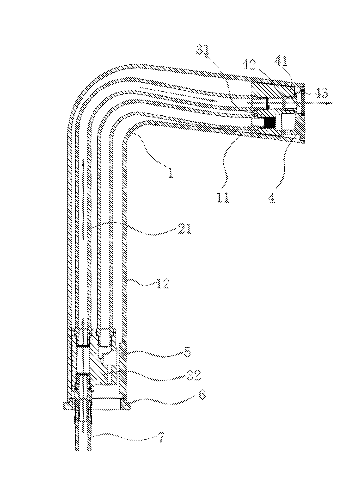
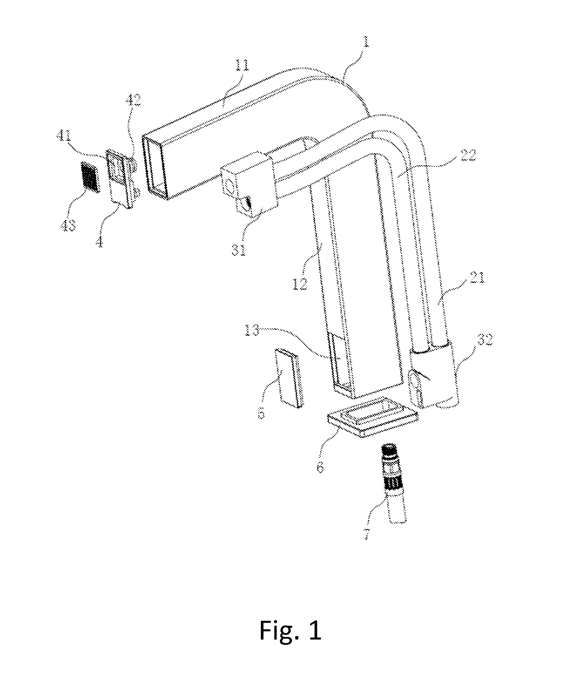
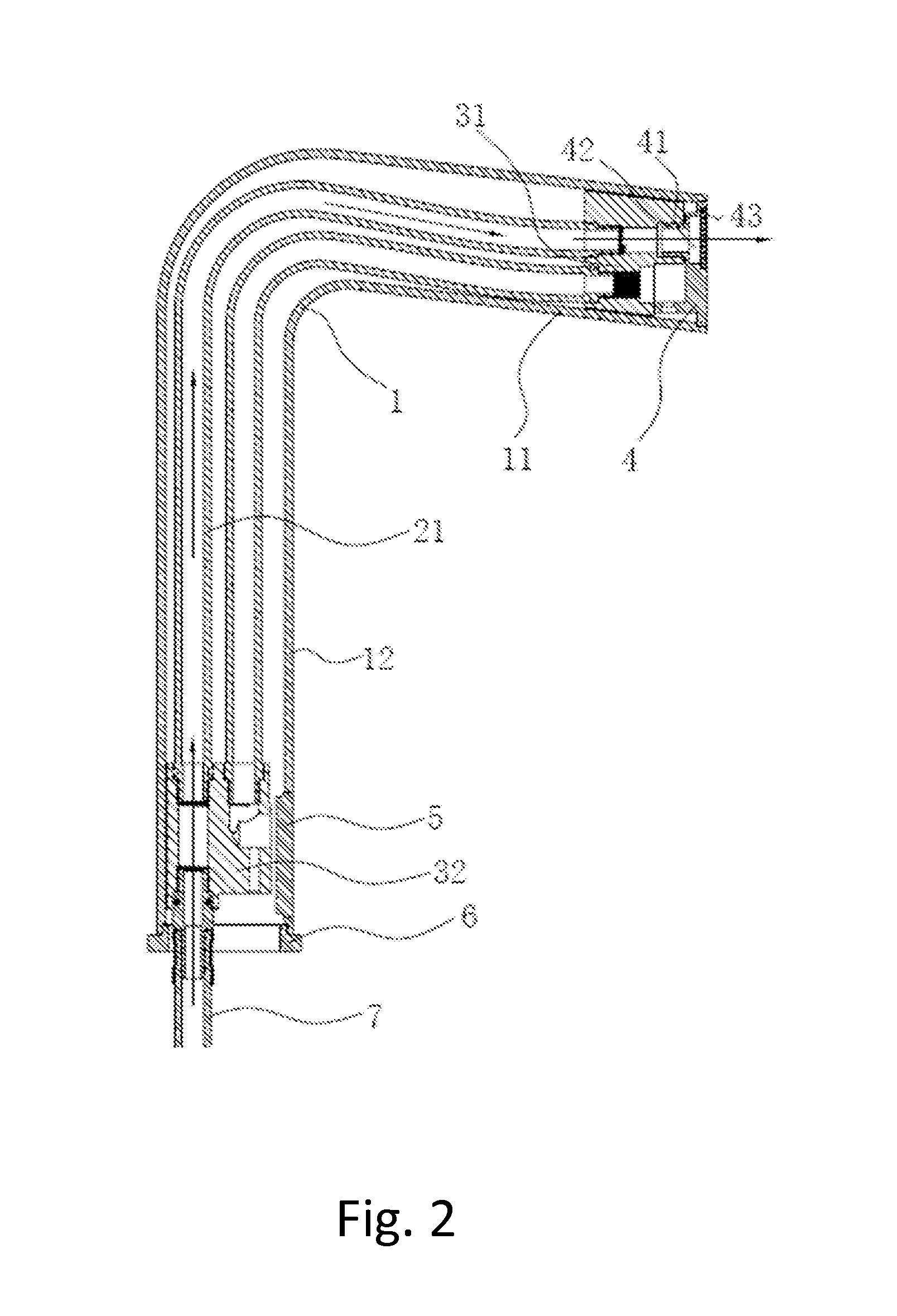
[0040]In the present invention, a high heel faucet is used. As shown in FIG. 2, the flange bottom seat 6 is connected to the opening of the end of the long tube 12, to fix the L shape housing 1 onto the surface of the installation table, to connect and seal the water inlet tube 7 and second water route interface 32. At this time, in order to keep the aesthetical outer appearance of the L shape housing 1, the decoration plate 5 is used to cover the opening 13 on the wall at the other end of the long tube 12. The water output panel 4 is connected to the opening at one end of the short tube 11, such that the connection tube 42 is connected to the first water route interface 31. In this embodiment, the water flowed in from the water inlet tube 7 is flowed sequentially through the second water route interface 32, the first water passage channel 21, and the first water route interface 31, then water is flowed out from the water output panel 4, and finally water is ejected out forward thro...

second embodiment

[0041]In the present invention, namely when a low heel faucet is used. As shown in FIG. 3, the flange bottom seat 6 is connected to the opening of one end of the short tube 11, to fix the L shape housing 1 onto the surface of the installation table, to connect and seal the water inlet tube 7 and first water route interface 31. At this time, in order to keep the aesthetical outer appearance of the L shape housing 1, the decoration plate 5 is used to cover the opening on the wall at the other end of the long tube 12. The water output panel 4 is connected to the opening at the end of the long tube 12, such that the connection tube 42 is connected to the second water route interface 32. In this embodiment, the water flowed in from the water inlet tube 7 is flowed sequentially through the first water route interface 31, the second water passage channel 22, and the second water route interface 32, then water is flowed out from the water output panel 4, and finally water is ejected out for...


PUM


Abstract

A faucet water output structure includes an L shape housing including a short tube and a long tube, wherein one end of the short tube is connected to one of the long tube, and on a wall of other end of the long tube is provided with an opening; a first water passage channel and a second water passage channel, both of which are located inside the L shape housing; and a first water route interface and a second water route interface, wherein, on the first water route interface is sleeved a water output end of the first water passage channel and a water input end of the second water passage channel, and on the second water route interface is sleeved a water input end of the first water passage channel and a water output end of the second water passage channel.

Description

BACKGROUND OF THE INVENTION[0001]1. Field of the Invention[0002]The present invention relates to a faucet water output structure, and in particular to a faucet water output structure that can be installed on both an over-table basin and under-table basin.[0003]2. The Prior Arts[0004]In the outfit of modern housing, basin is placed in washroom, to be used together and in cooperation with faucet. At present, in the installation of a basin, it can be installed and placed as an over-table basin or an under-table basin. For the faucet presently available on the market, the over-table basin can only be used in cooperation with a high heel faucet, while under-table basin can only be used in cooperation with a low heel faucet. In this respect, the two kinds of faucets can not be used in an interchangeable manner, for that could result in unfit installation or improper installation to cause aesthetical problems.[0005]Therefore, presently, the design and performance of a faucet is not quite s...

Claims


Application Information

Patent Timeline
IPC IPC(8): E03C1/04
CPCE03C1/04Y10T137/9464E03C1/0403E03C1/0401E03C1/0404
Inventor LI, MYAZHOU, INSCYSHEN, DENNIS
Owner XIAMEN RUNNER IND CORP
Learn More