Image forming apparatus

a technology of image forming apparatus and forming chamber, which is applied in the direction of electrographic process apparatus, instruments, optics, etc., can solve the problems of achieving a compact apparatus

Active Publication Date: 2015-12-03
OKI ELECTRIC IND CO LTD
View PDF4 Cites 3 Cited by
  • Summary
  • Abstract
  • Description
  • Claims
  • Application Information

AI Technical Summary

Benefits of technology

[0007]An object of the present invention is to provide an image forming apparatus that requires only a small space when a cover with LED heads mounted thereon is opened and closed relative to the image forming apparatus.

Problems solved by technology

This type of image forming apparatus usually requires a large space sufficient for smoothly opening and closing of the top cover without interfering with surrounding structural elements in the image forming apparatus, which are obstacles to achieving a compact apparatus.

Method used


Image

  • Image forming apparatus
  • Image forming apparatus
  • Image forming apparatus

Examples


first embodiment

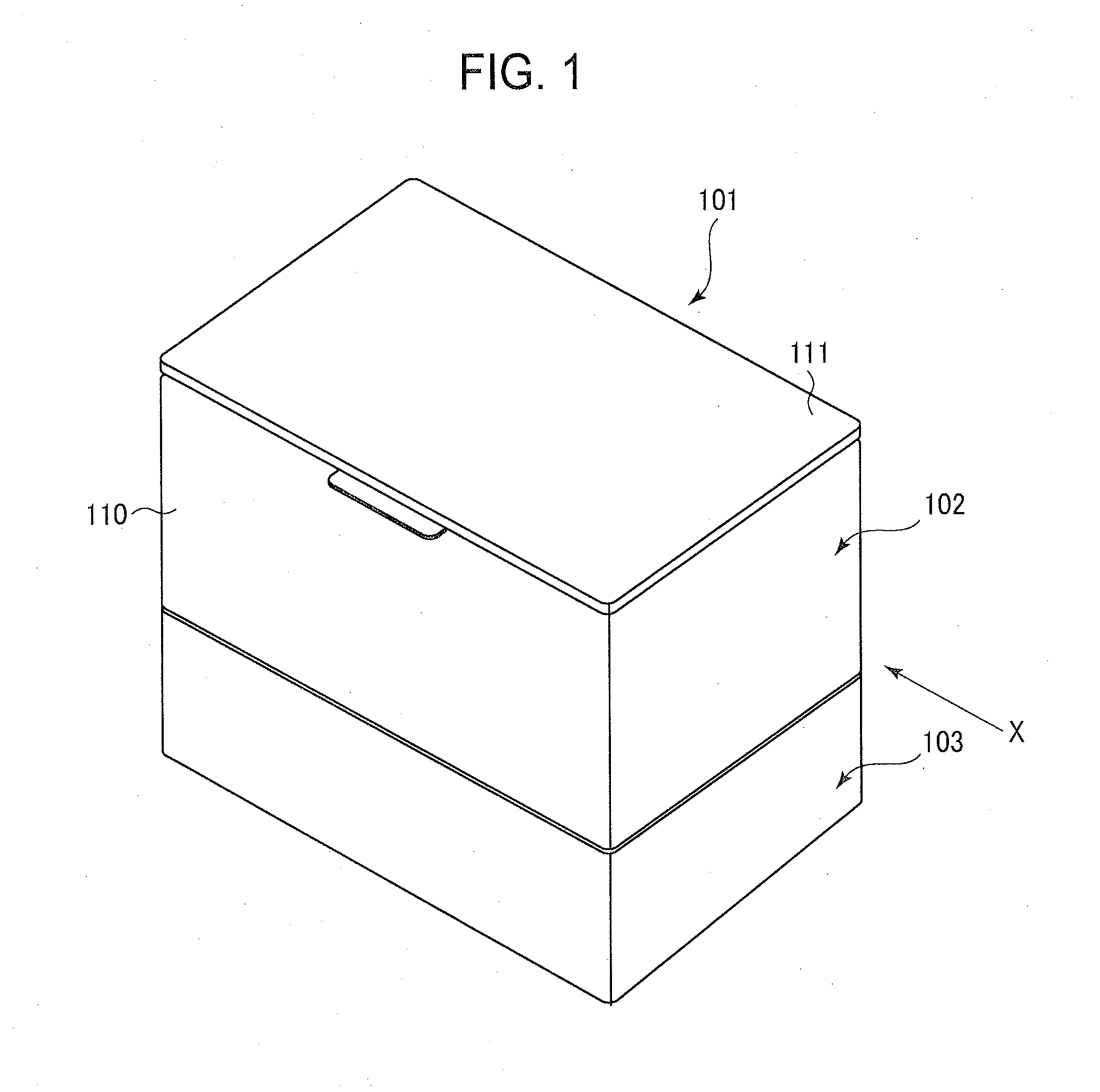
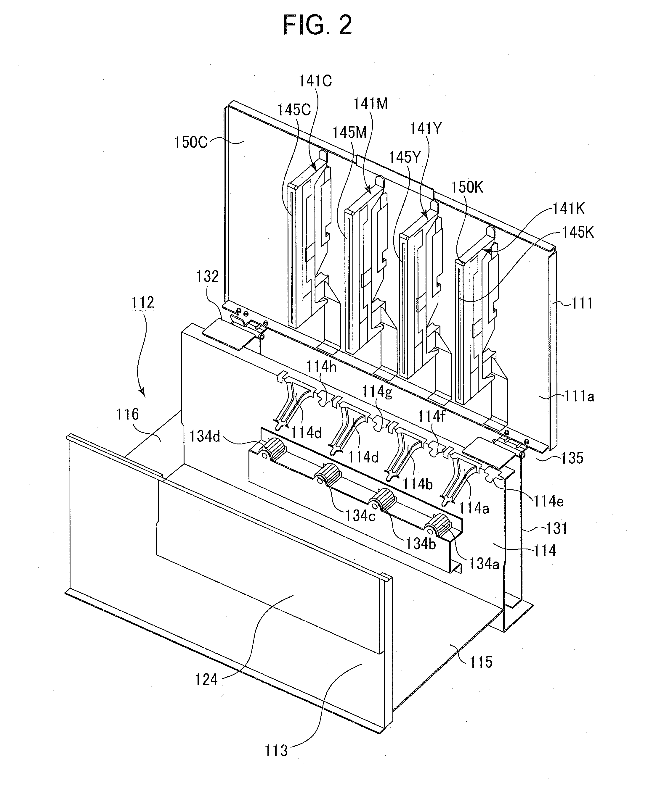
[0047]FIG. 1 is a perspective view of an image forming apparatus 101 according to a first embodiment. FIG. 2 is a perspective view of a chassis 112 and a top cover 111 that is pivotally mounted on the chassis 112. FIG. 3 is a perspective view of the chassis 112 and the top cover 111 as seen in another direction.

[0048]Referring to FIG. 1, the image forming apparatus 101 includes a printing section 102 disposed on a paper cassette 103. The printing section 102 prints on a sheet of recording paper 125 (FIG. 15) supplied from the paper cassette 103, and discharges the printed recording paper 125 onto a stacker.

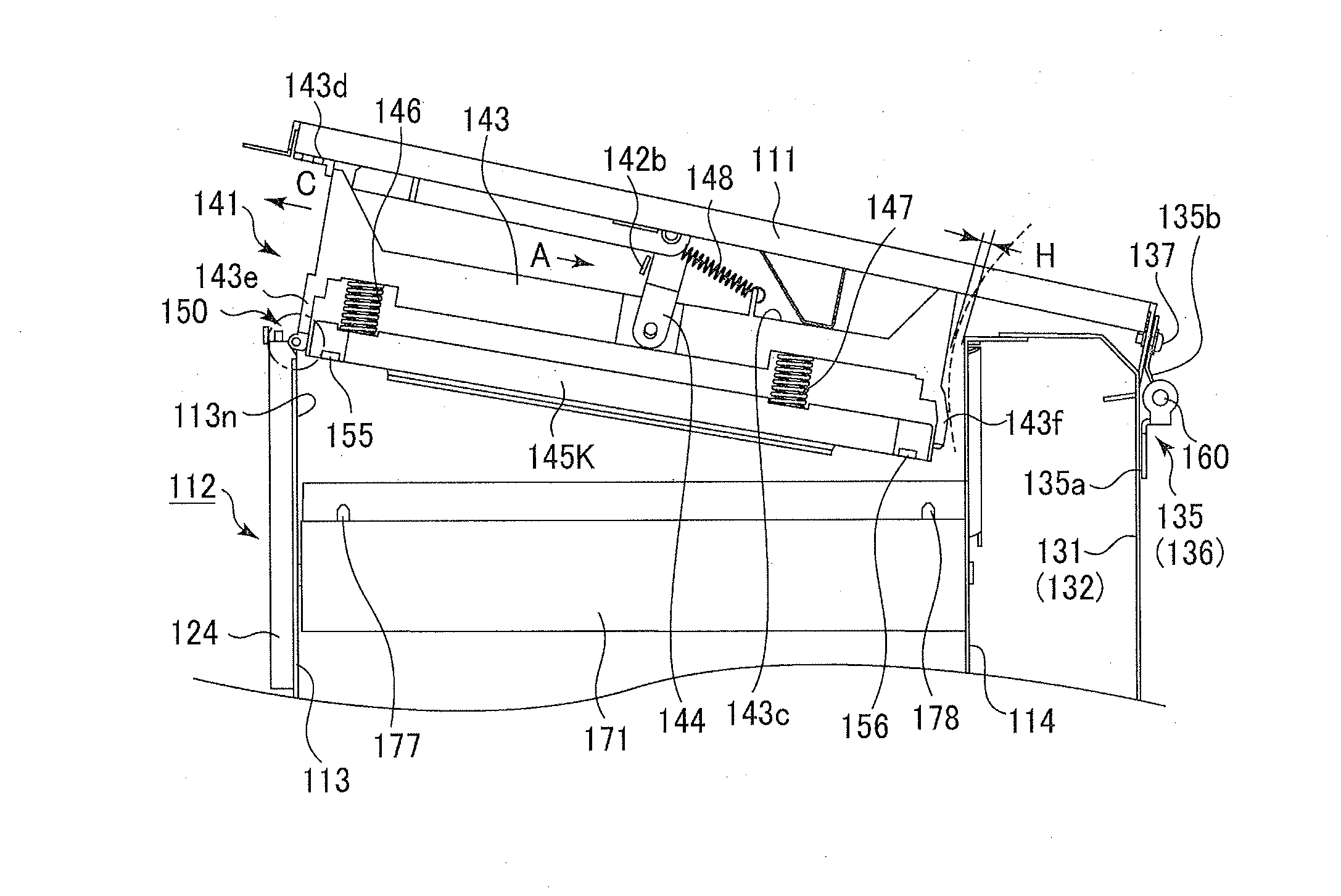
[0049]Referring to FIGS. 2 and 3, the printing section 102 includes a housing 110 that accommodates the chassis 112. The chassis 112 includes a left frame 113, a right frame 114, a bottom frame 115, and a rear frame 116. The left frame 113 and right frame 114 are parallel to each other, and rise from the bottom frame 115. The rear frame 116 rises from the bottom frame 115, and is ...

second embodiment

[0111]FIG. 17 is a perspective view of a chassis 212 and a top cover 211 that is pivotally mounted on the chassis 212. FIG. 18 is a perspective view of the chassis 212 and the top cover 211 as seen in another direction.

[0112]The second embodiment differs from the first embodiment in that head units 241K, 241Y, 241M, and 241C are mounted on the top cover 211 and a pair of generally U-shaped supporting plates 231a and 231b are assembled to the chassis 212. Thus, the second embodiment will be described only with respect to portions different from the first embodiment. The LED head units 141K, 141Y, 141M, and 141C are identical in construction and the description thereof will be confined to the LED head unit 141K.

[0113]Each of the supporting plates 231a and 231b is disposed at a longitudinal end portion of the outer surface of a right frame 214. The top cover 111 is pivotally mounted on the right frame 214 by means of hinges 235 and 236. Each of the hinges 235 and 236 includes two hinge...


PUM


Abstract

An image forming apparatus includes a cover configured to pivot about a shaft to open and close, and a mechanism that includes a movable member and a supporting mechanism. The movable member longitudinally extends in a direction at an angle with the shaft, and includes a first longitudinal end portion and a second longitudinal end portion, the first longitudinal end portion being closer to the shaft than the second longitudinal end portion. The supporting mechanism is mounted on the cover and supports the movable member so that the movable member is movable relative to the cover toward and away from the shaft. When an external force pushes the second longitudinal end portion toward the shaft, the movable member moves to a first position, and when the external force is removed, the movable member returns.

Description

BACKGROUND OF THE INVENTION[0001]1. Field of the Invention[0002]The present invention relates to an electrophotographic image forming apparatus, and more particularly to a mechanism for opening and closing the top cover of an electrophotographic image forming apparatus.[0003]2. Description of the Related Art[0004]Japanese Patent Application Laid-Open No. 2001-209220 discloses an electrophotographic image forming apparatus that employs a configuration in which LED heads are secured to an openable cover. When a user mounts the LED heads on the image forming apparatus or dismounts the LED heads from the image forming apparatus, he opens the top cover.[0005]This type of image forming apparatus usually requires a large space sufficient for smoothly opening and closing of the top cover without interfering with surrounding structural elements in the image forming apparatus, which are obstacles to achieving a compact apparatus.SUMMARY OF THE INVENTION[0006]The present invention was made to ...

Claims


Application Information

Patent Timeline
Patent Type & Authority Applications(United States)
IPC IPC(8): G03G15/00
CPCG03G21/1633
Inventor FUKUDA, MASAHIRO
Owner OKI ELECTRIC IND CO LTD
Why Eureka
Try Eureka