Rotating shaft, terminal equipment and rotating shaft control method

A technology of terminal equipment and shaft rotation, applied in the field of communication, can solve the problems of low reliability, increased body thickness, large deployment gap, etc., and achieve the effect of not being easily damaged, requiring less space, and high reliability

Active Publication Date: 2019-07-30
ZTE CORP
View PDF6 Cites 1 Cited by
  • Summary
  • Abstract
  • Description
  • Claims
  • Application Information

AI Technical Summary

Problems solved by technology

[0006] Embodiments of the present invention provide a rotating shaft, a terminal device, and a rotating shaft control method to at least solve the problem that when the fixed rotating shaft structure in the related art is applied to the folding device, the thickness of the body may increase, the unfolding gap is large, and the reliability is low , At least one of the problems that affect the user's use effect

Method used


Image

  • Rotating shaft, terminal equipment and rotating shaft control method
  • Rotating shaft, terminal equipment and rotating shaft control method
  • Rotating shaft, terminal equipment and rotating shaft control method

Examples


Embodiment 1

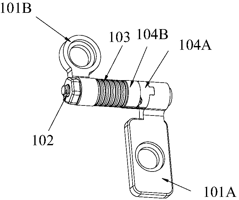
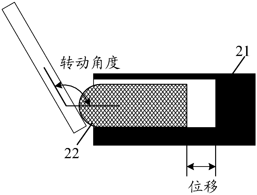
[0050] figure 2 It is a schematic diagram of the rotation and translation of the rotating shaft 22 in the fixed part 21 according to Embodiment 1 of the present invention. This embodiment provides a rotating shaft 22, which can be used but not limited to two or more than two folding devices. Connections between ontologies.

[0051] The rotating shaft 22 can be installed in the fixing part 21 (the fixing part 21 can be a fixing part fixedly arranged in the body of the folding device), such as figure 2 As shown, the rotating shaft 22 slides in the fixing part 21 during the rotation process, wherein there is a corresponding relationship between the rotating angle of the rotating shaft 22 and the sliding displacement of the rotating shaft 22 in the fixing part 21 .

[0052] When the rotating shaft 22 is applied to a specific folding device, according to the functions of each body of the folding device and the expected folding and unfolding effect, the rotating shaft 22 can be ...

Embodiment 2

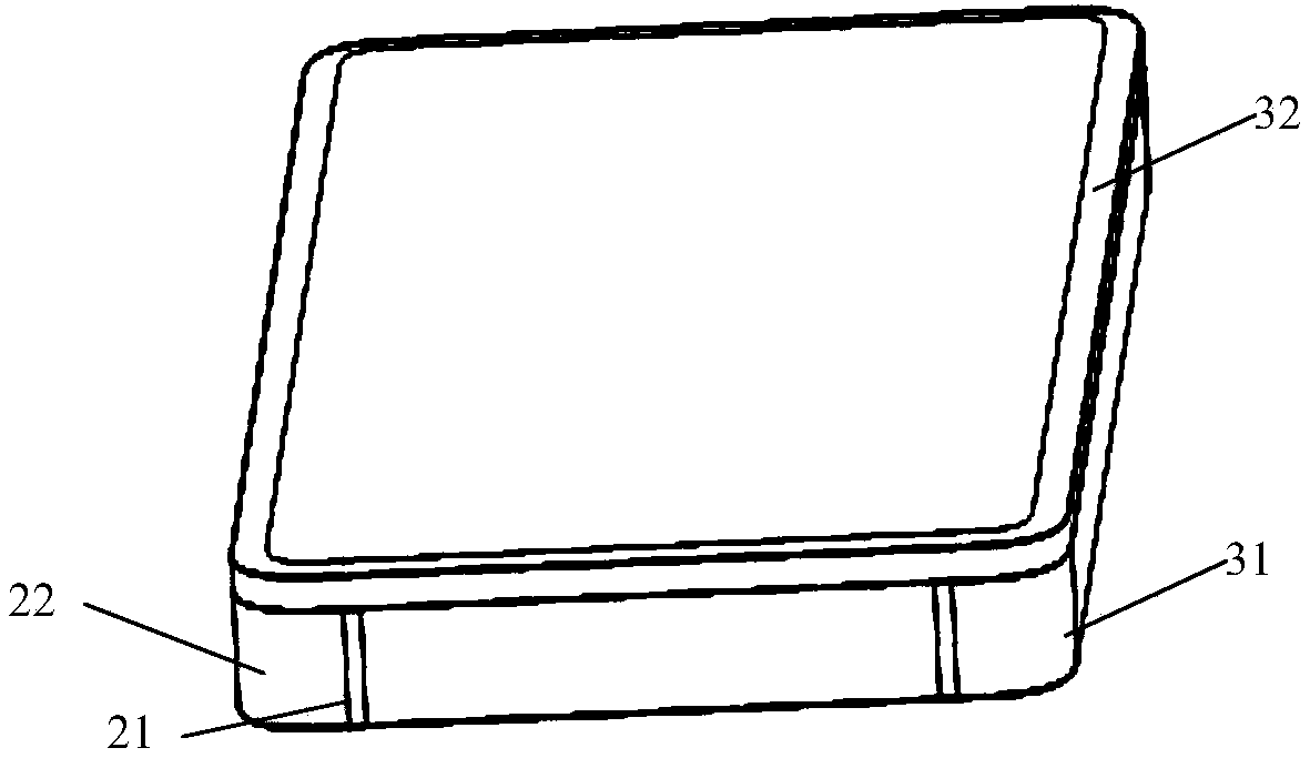
[0089] Figure 8 is a schematic diagram of a terminal device using the rotating shaft described in Embodiment 1 according to Embodiment 2 of the present invention. Such as Figure 8 As shown, a terminal device provided in this embodiment includes a first body 31 and a second body 32, wherein the first body 31 is provided with a fixing part 21, and the rotating shaft 22 as described in Embodiment 1 is installed In the fixing part 21 , the first body 31 and the second body 32 are connected by the rotating shaft 22 .

[0090] The first rotating shaft pressing plate 222 of the rotating shaft 22 is fixedly installed in the fixing portion 21 of the first body 31 , and the second rotating shaft pressing plate 223 of the rotating shaft 22 is fixedly installed in the second body 32 .

[0091] As a preferred implementation manner, the terminal device may also include: an angle sensor and a control signal generation module, wherein,

[0092] The angle sensor is used to sense the inclu...

Embodiment 3

[0097] Figure 9 is a flow chart of a rotating shaft control method according to Embodiment 3 of the present invention. Such as Figure 9 As shown, the rotating shaft control method includes:

[0098] Step S902, sensing the angle between the first body 31 and the second body 32 of the terminal device;

[0099] Step S904, generating a control signal according to the information of the included angle, wherein the control signal is used to control the rotation shaft connecting the first body 31 and the second body 32 in the fixed part where the rotation shaft is installed according to The displacement sliding corresponding to the included angle;

[0100] Step S906, sending the control signal to the displacement control device of the rotating shaft.

[0101] Through this method, the displacement control device of the shaft of the terminal device can be controlled according to the angle between the first body 31 and the second body 32 of the terminal device, so that the displac...


PUM


Abstract

The invention provides a rotating shaft, terminal equipment and a rotating shaft control method. The rotating shaft is installed in a fixing portion, and the rotating shaft slides in the fixing portion in the rotating process, wherein a corresponding relation exists between the rotating angle of the rotating shaft and the displacement of the rotating shaft sliding in the fixing portion. Accordingto the rotating shaft, the terminal equipment and the rotating shaft control method, at least one of the problems that the thickness of a machine body is increased, the expansion gap is large, the reliability is relatively low, and the use effect of a user is influenced due to the fact that a fixed rotating shaft structure is applied to folding equipment in the related technology. The scheme can meet the turnover design of the folding equipment, and has the advantages of being small in demand space, not easy to damage, high in reliability and the like.

Description

technical field [0001] The present invention relates to the communication field, in particular, to a rotating shaft, a terminal device and a rotating shaft control method. Background technique [0002] With the advancement of technology, equipment manufacturers have developed more and more types of terminal equipment. At present, people have higher and higher requirements for large screens, multitasking, etc., and dual-screen devices (for example, dual-screen mobile phones) have emerged as the times require. In order to reduce the size of the device, the two screens in the dual-screen device need to be folded, and the body where the two screens are located needs to be connected by a hinge to achieve a foldable effect. In addition, the original folding device, such as a device including a screen and a keyboard, also needs to connect the two bodies through a hinge to achieve a foldable effect. With the development of technology, there may be more folding devices with bodies,...

Claims


Application Information

Patent Timeline
Patent Type & Authority Applications(China)
IPC IPC(8): F16C11/04F16C11/12
CPCF16C11/04F16C11/12G06F1/16
Inventor 王彦彬张磊
Owner ZTE CORP
Why Eureka
Try Eureka