
Physiological Monitoring Devices Having Sensing Elements Decoupled from Body Motion

a monitoring device and sensor technology, applied in the field of monitoring devices, can solve the problems of reducing the quality of swamping the time-varying changes in photon intensity, and difficult to ascertain the signal of interest, so as to reduce the displacement, reduce the dislocation of the sensor to the skin contact, and improve the effect of tuning

Active Publication Date: 2015-12-24
YUKKA MAGIC LLC
View PDF8 Cites 14 Cited by
  • Summary
  • Abstract
  • Description
  • Claims
  • Application Information

AI Technical Summary

Benefits of technology

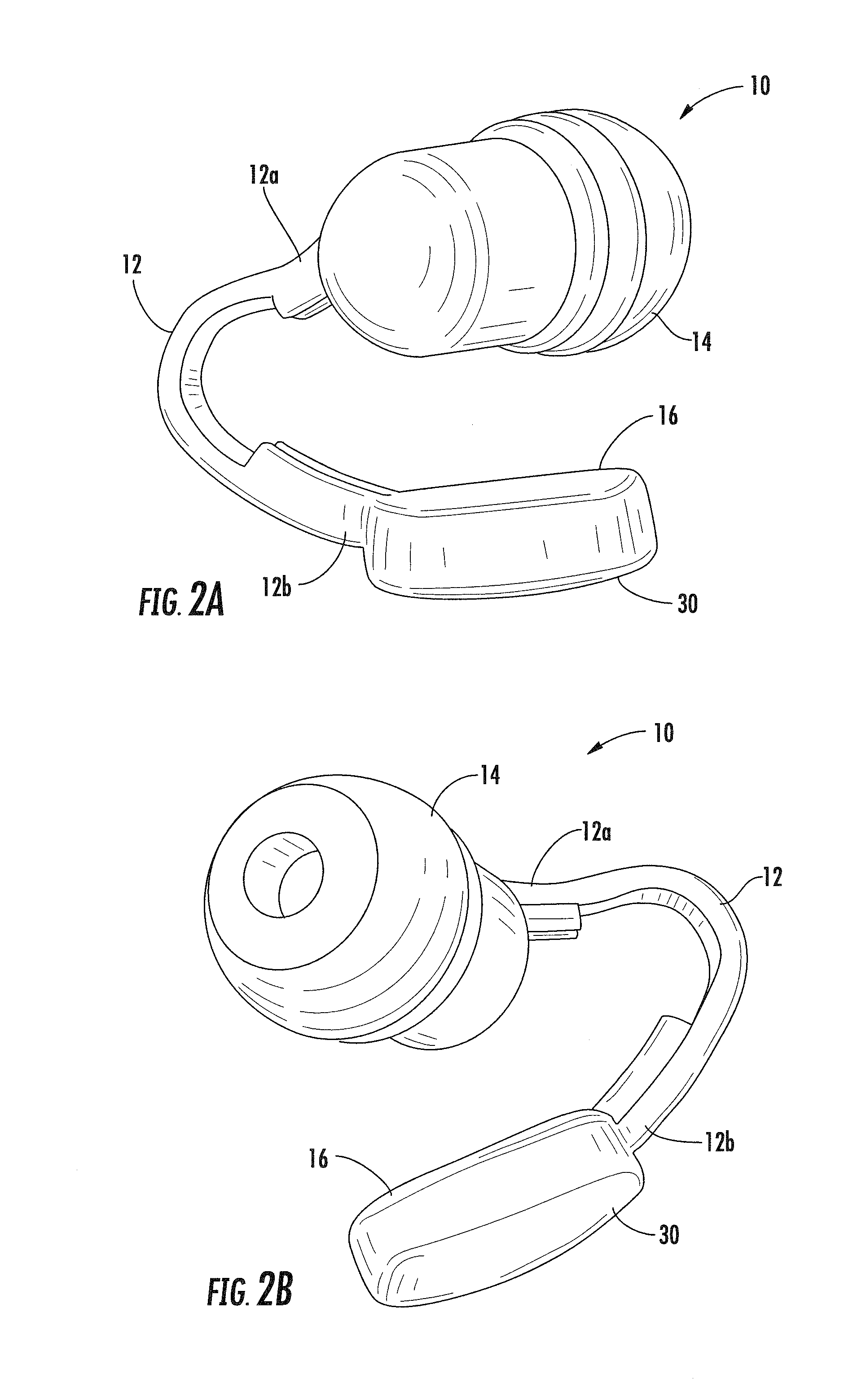
[0025]Earbud monitoring devices, according to embodiments of the present invention, are advantageous over conventional monitoring devices for several reasons. One is comfort of fit. An earbud monitoring device according to embodiments of the present invention is comfortable and may provide more accurate biometrics than conventional earbuds. Moreover, by designing the sensor element as a separate body from the earbud, the earbud can be tailored for comfort. Another advantage is that by providing supplemental spring action on the sensor module an additional level of sensor to skin intimacy may be achieved. By decoupling the sensor module and earbud, less spring force (pressure) is needed to maintain sensor contact with the ear, thus resulting in greater comfort. A device where the sensor can stay in contact with the interrogation area of interest, even under extreme accelerations, may be able to continuously report data and offer the end-user a higher confidence level in the device's accuracy.
[0036]Embodiments of the present invention utilize a sensing element as a distinct third body relative to a monitoring device and a body of a subject wearing the monitoring device. For example, if the monitoring device is an earbud configured to be secured within the ear of a subject, the ear of the subject is the first body, the earbud is the second body, and the sensing element or module is a distinct third body. As such, embodiments of the present invention provide several advantages over conventional monitoring devices. First, the mass of the sensing element, according to embodiments of the present invention, is reduced since the sensing element is decoupled from the earbud body. This lower mass may see smaller displacements as a result of ear, earbud or appendage accelerations, for example, as a result of subject motion. Second, a sensing element, according to embodiments of the present invention, can be shaped and presented to the interrogation surface of interest in a form tailored for optical coupling and not restricted by conventional forms, such as conventional earbud forms.
[0037]In addition, the effect of earbud cabling pulling on an earbud and possibly dislodging the sensor to skin contact can be minimized by having a biasing element, such as a spring, between the earbud and the sensor, according to embodiments of the present invention. By incorporating a biasing element between an earbud and sensor, fit within one or more portions of the concha of an ear can be achieved with an optimized earbud form, while fit between the sensor and interrogation surface can be optimized for photoplethysmography. Moreover, because any dampened system will have a lag in response to vibrational compensation, decoupling the sensor element from earbud motion allows the sensor response to be better tuned to managing small vibrational offsets; whereas, the earbud dampening structures are best designed to handle larger displacements inherent from a larger, heavier mass body with multiple ear contact points. The earbud makes larger amplitude acceleration compensations compared to the sensor element due to its larger mass. The secondary minor acceleration compensations of the sensor to ear surface (or appendage) movement may be significantly reduced as well as signal variation.

Problems solved by technology

If the incidental and scattered photon count magnitude changes due to light coupling variation between the source or detector and the skin surface, then the signal of interest can be difficult to ascertain due to large photon count variability caused by loss or variation of optical coupling.
Physical activity, such a walking, cycling, running, etc., may cause motion artifacts in the optical scatter signal from the body, and time-varying changes in photon intensity due to motion artifacts may swamp-out time-varying changes in photon intensity due to blood flow changes.
Each of these changes in optical coupling can affect the photonic interrogation count by a large percent of the total photon count and diminish the quality of the signal of interest; with lower probability of obtaining accurate values of desired data.
Unfortunately, incorporation of a photoplethysmograph device into an earphone poses several challenges.
For example, earphones may be uncomfortable to wear for long periods of time, particularly if they deform the ear surface.
Moreover, human ear anatomy may vary significantly from person to person, so finding an earbud form that will fit comfortably in many ears may pose significant challenges.
Although, these features may facilitate retention of an earbud within an ear during high acceleration and impact modalities, they do not adequately address optical skin coupling requirements needed to achieve quality photoplethysmography.
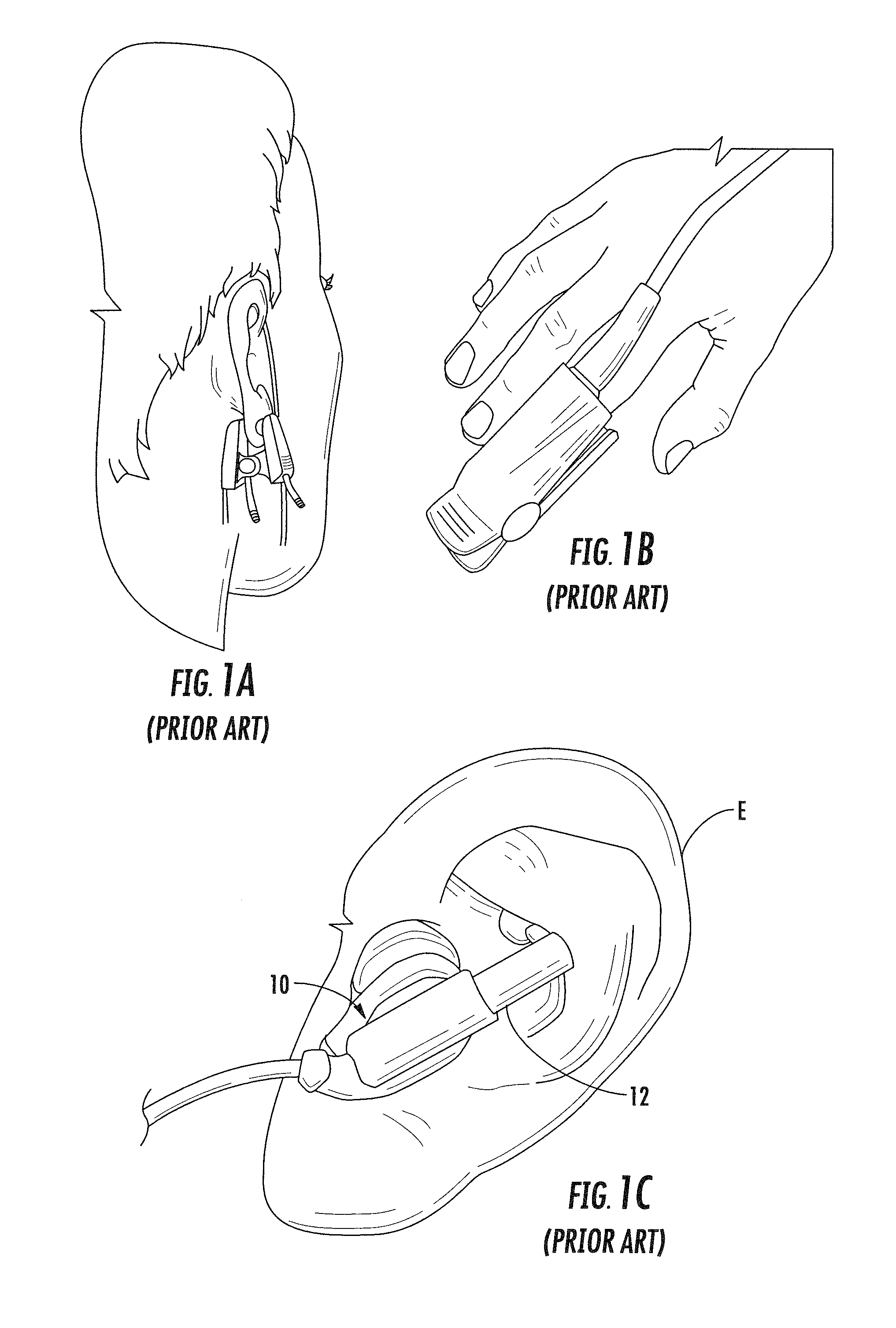
Conventional photoplethysmography devices, as illustrated for example in FIGS. 1A-1C, typically suffer from reduced skin coupling as a result of subject motion.
Unfortunately, these conventional devices tend to have a large mass and may not maintain consistent skin contact when subjected to large accelerations, such as when a subject is exercising.
In addition, because the earbud 10 is held in place with one primary spring force direction, significant discomfort can be experienced by the end user.

Method used


Image

  • Physiological Monitoring Devices Having Sensing Elements Decoupled from Body Motion
  • Physiological Monitoring Devices Having Sensing Elements Decoupled from Body Motion
  • Physiological Monitoring Devices Having Sensing Elements Decoupled from Body Motion

Examples


Embodiment Construction

[0064]The present invention will now be described more fully hereinafter with reference to the accompanying figures, in which embodiments of the invention are shown. This invention may, however, be embodied in many different forms and should not be construed as limited to the embodiments set forth herein. Like numbers refer to like elements throughout. In the figures, certain layers, components or features may be exaggerated for clarity, and broken lines illustrate optional features or operations unless specified otherwise. In addition, the sequence of operations (or steps) is not limited to the order presented in the figures and / or claims unless specifically indicated otherwise. Features described with respect to one figure or embodiment can be associated with another embodiment or figure although not specifically described or shown as such.

[0065]It will be understood that when a feature or element is referred to as being “on” another feature or element, it can be directly on the o...


PUM


Abstract

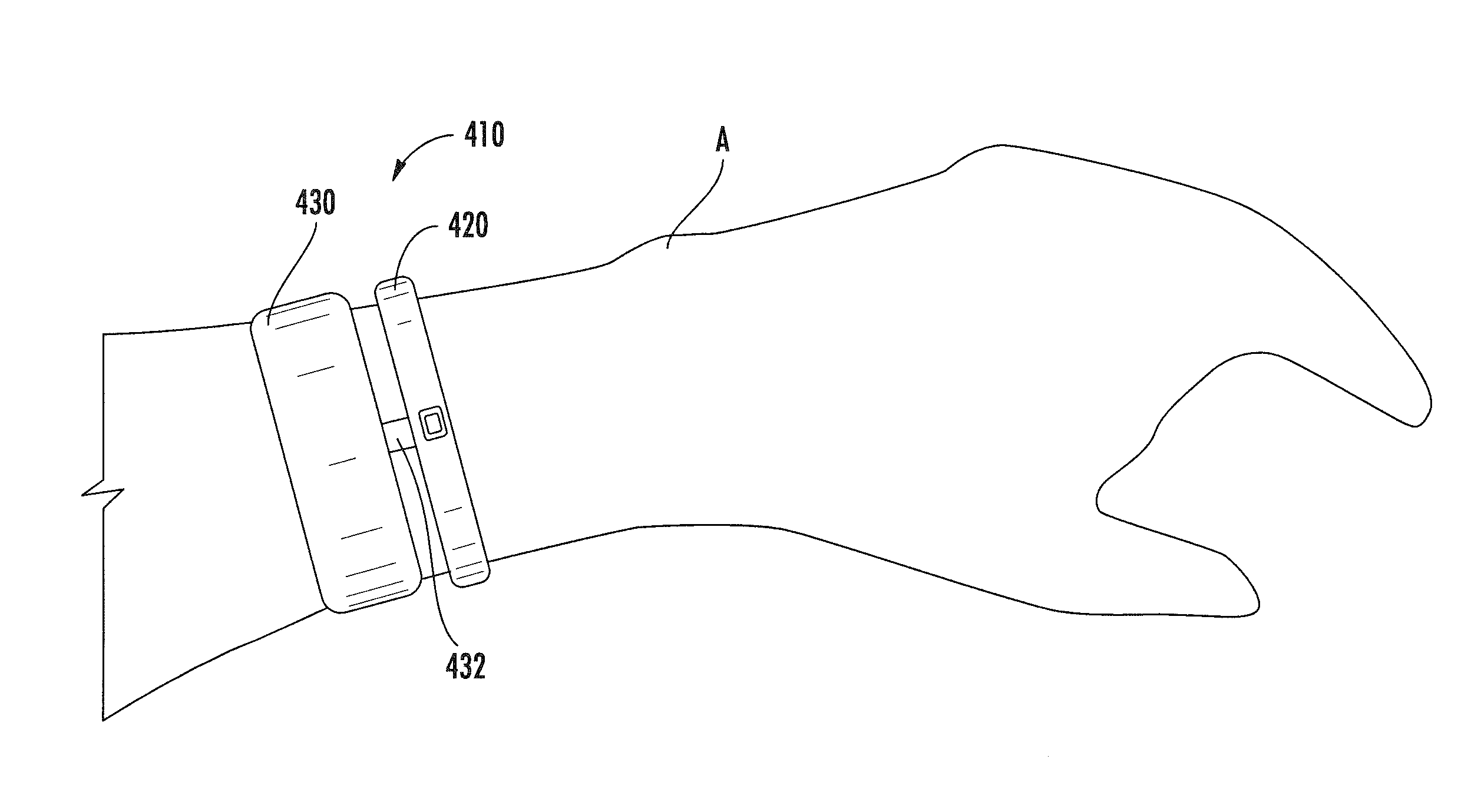
A monitoring device includes a sensor band configured to be secured around an appendage of a subject, and a sensing element movably secured to the sensor band via a biasing element. The sensor band has a first mass, and the sensing element has a second mass that is less than the first mass. The biasing element is configured to urge the sensing element into contact with a portion of the appendage, and the biasing element decouples motion of the band from the sensing element. A monitoring device includes a band that is configured to be secured around an appendage of a subject. One or more biasing elements extend outwardly from the band inner surface and are configured to contact the appendage. A sensing element is secured to the band inner surface. The one or more biasing elements decouples motion of the band from the sensing element.

Description

RELATED APPLICATION[0001]This application claims the benefit of and priority to U.S. Provisional Patent Application No. 61 / 757,504 filed Jan. 28, 2013, the disclosure of which is incorporated herein by reference as if set forth in its entirety.FIELD OF THE INVENTION[0002]The present invention relates generally to monitoring devices and, more particularly, to monitoring devices for measuring physiological information.BACKGROUND OF THE INVENTION[0003]Photoplethysmography (PPG) is based upon shining light into the human body and measuring how the scattered light intensity changes with each pulse of blood flow. The scattered light intensity will change in time with respect to changes in blood flow or blood opacity associated with heart beats, breaths, blood oxygen level (SpO2), and the like. Such a sensing methodology may require the magnitude of light energy reaching the volume of flesh being interrogated to be steady and consistent so that small changes in the quantity of scattered ph...

Claims


Application Information

Patent Timeline
Patent Type & Authority Applications(United States)
IPC IPC(8): A61B5/024A61B5/00A61B5/1455
CPCA61B5/02416A61B5/721A61B5/681A61B5/14551A61B5/11A61B5/6817H04R1/1016A61B5/026A61B5/14552A61B2562/0219
Inventor JUST, STEVEN MATTHEWTUCKER, JESSE BERKLEYSPLINTER, ROBERTLEBOEUF, STEVEN FRANCIS
Owner YUKKA MAGIC LLC
Learn More