Photometric stereo endoscopy

a stereo endoscope and stereo endoscope technology, applied in the field of photometric stereo endoscope imaging, can solve the problems of difficult to detect clinically significant lesions, difficult to extract significant topographical information, and difficult to achieve significant topographical information, etc., to achieve the effect of facilitating computer assisted detection of features

Inactive Publication Date: 2015-12-31
MASSACHUSETTS INST OF TECH
View PDF13 Cites 55 Cited by
  • Summary
  • Abstract
  • Description
  • Claims
  • Application Information

AI Technical Summary

Benefits of technology

The present patent describes how to use advanced technology to analyze and detect abnormal tissue growth during colonoscopy procedures by combining data from traditional 2D images with detailed maps of the patient's body surfaces obtained through specialized optical instruments. This allows for more accurate identification of potential cancerous areas that might have been previously missed.

Problems solved by technology

The technical problem addressed in this patent is the need for improved systems and methods for performing and utilizing three-dimensional imaging in an endoscopy system. Current methods of endoscopy, such as video endoscopy, are limited in their ability to extract significant topographical information and frequently miss clinically significant lesions. This is due to the large search space relative to the size of the lesion and the limited time in which colonoscopies are performed to be cost-effective screening tools. The patent aims to address this need by providing a solution for performing and utilizing three-dimensional imaging in an endoscopy system.

Method used


Image

  • Photometric stereo endoscopy
  • Photometric stereo endoscopy
  • Photometric stereo endoscopy

Examples


Embodiment Construction

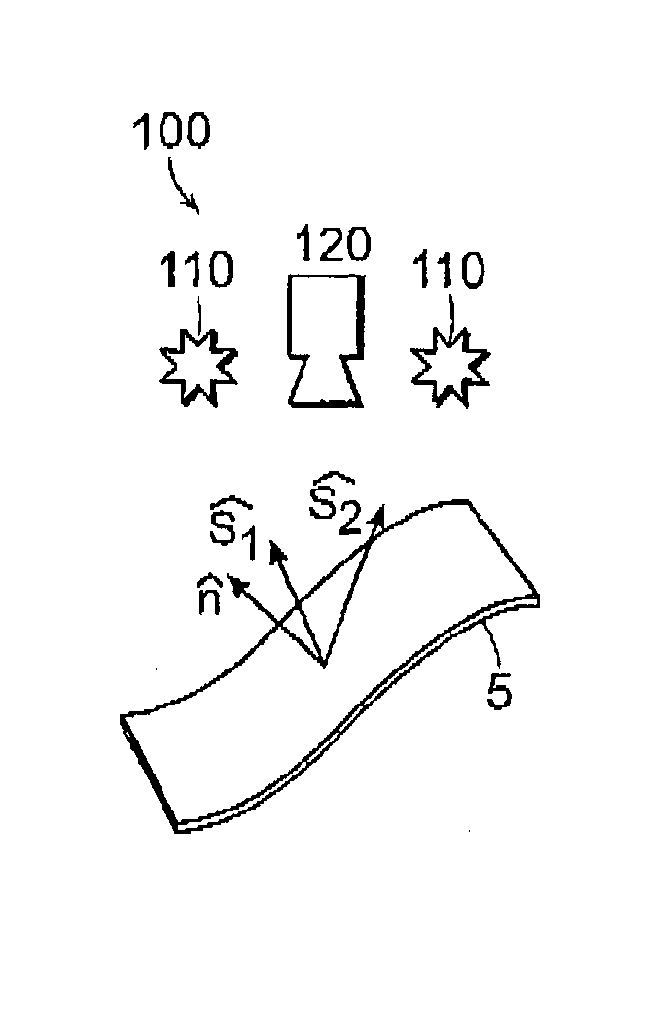
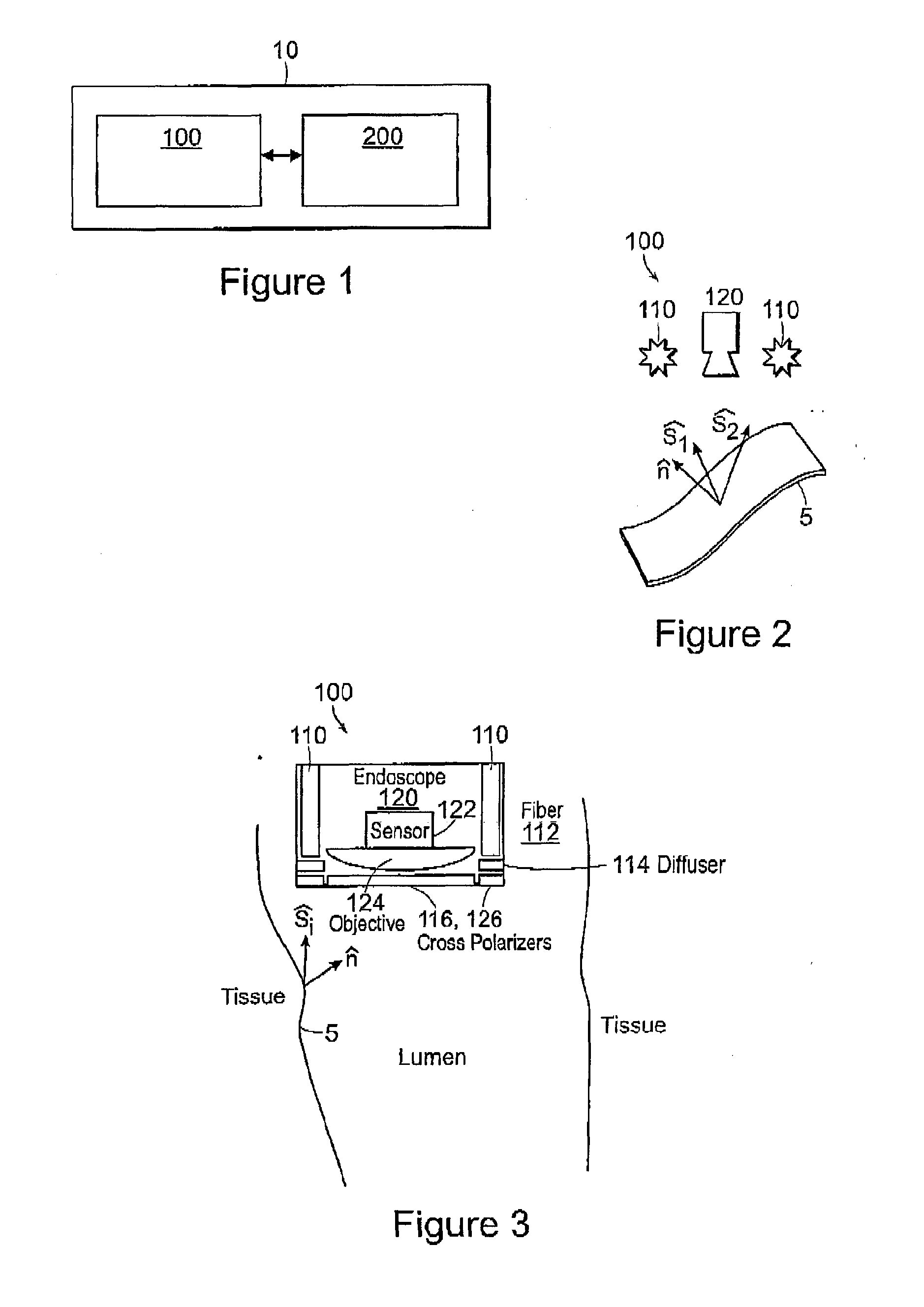
[0042]The present invention relates endoscopic imaging techniques referred to herein as photometric stereo endoscopy (PSE). According to the present invention, PSE generally involves systems and methods which enable acquisition of high-spatial-frequency components of surface topography and conventional two-dimensional images (e.g., color images). Thus, in exemplary embodiments, the orientation of the surface of each pixel in the field of view can be calculated using PSE. This orientation can be represented, e.g., by a surface normal, surface parallel vector, or an equation of a plane. In some embodiments, a resulting surface normal map can optionally be reconstructed into a surface topography. Advantageously, PSE allows for implementation with an imaging device conforming to an endoscopic form factor.

[0043]In exemplary embodiments, PSE enables accurate reconstruction of the topographical information relating to small features with complex geometries and heterogeneous optical propert...


PUM


Abstract

The present invention relates to systems and methods for photometric endoscope imaging. The methods can further include chromoendoscopy and computer aided detection procedures for the imaging of body lumens and cavities.

Description


Claims


Application Information

Patent Timeline
Owner MASSACHUSETTS INST OF TECH
Why Eureka
Try Eureka