Conductive adhesives

a technology of conductive adhesives and contact particles, which is applied in the direction of conductive materials, metal/alloy conductors, oxide conductors, etc., can solve the problems of difficult to predict the right combination of force, time and temperature, and difficulty in getting this right, and achieve the correct amount of deformation of contact particles. , to achieve the effect of correct process parameters, the problem of determining the correct amount of contact particles

Active Publication Date: 2015-06-25
CONPART
View PDF2 Cites 3 Cited by
  • Summary
  • Abstract
  • Description
  • Claims
  • Application Information

AI Technical Summary

Benefits of technology

[0016]wherein the conductive particles are arranged such that they will not fail, e.g. crack or fracture, when deformed to a

Problems solved by technology

Due to the strongly time and temperature dependent properties of the adhesive caused by the on-going curing, it is immensely difficult to predict the right combination of force, time and temperature that will correctly squeeze out the right amount of adhesive and leave the particles with the correct amount of deformation after the finished bonding.
These parameters have to be adjusted by experiments and in some cases even monitored continuously during manufacturing, but it is still very difficult to get this right.
Thus, determining the correct process parameters that provide the correct amount of deformation of the contact particles is a problem.
As the particles are to some extent brittle, they will crack when the deformation reaches certain levels.
More than this and the pressure was too high.
In other cases it is more difficult.
The main planarity issue has typically been with the contact-bumps on the chips themselves.
The very small distribution of size and mechanical properties in the latest generation of particles means that there is also a very small distribution of crack points.
Therefore even if such particles are deformed very slowly (e.g. pressu

Method used


Image

  • Conductive adhesives
  • Conductive adhesives
  • Conductive adhesives

Examples


Embodiment Construction

[0021]The conductive adhesive is preferably an ACA, such as an ACF. Ideally, the adhesive material is a thermosetting or thermoplastic resin or rubber. Thermosetting resins are preferred. Possible thermosetting resins are for example, synthetic resins, such as, epoxy resins, melamine resins, phenol resins, diallyl phthalate resin, bismaleimidotriazine resin, polyesters, cyanoacrylates, polyurethanes, phenoxy resins, polyamides and polyimides; and rubbers and elastomers containing functional group(s), such as hydroxy, carboxyl, vinyl, amino or epoxy. Among them, epoxy resins are especially preferred.

[0022]Preferred epoxy resins are those based on bisphenol type, epoxynovolak resins and those made from epoxy compounds having in the molecule two or more oxirane groups.

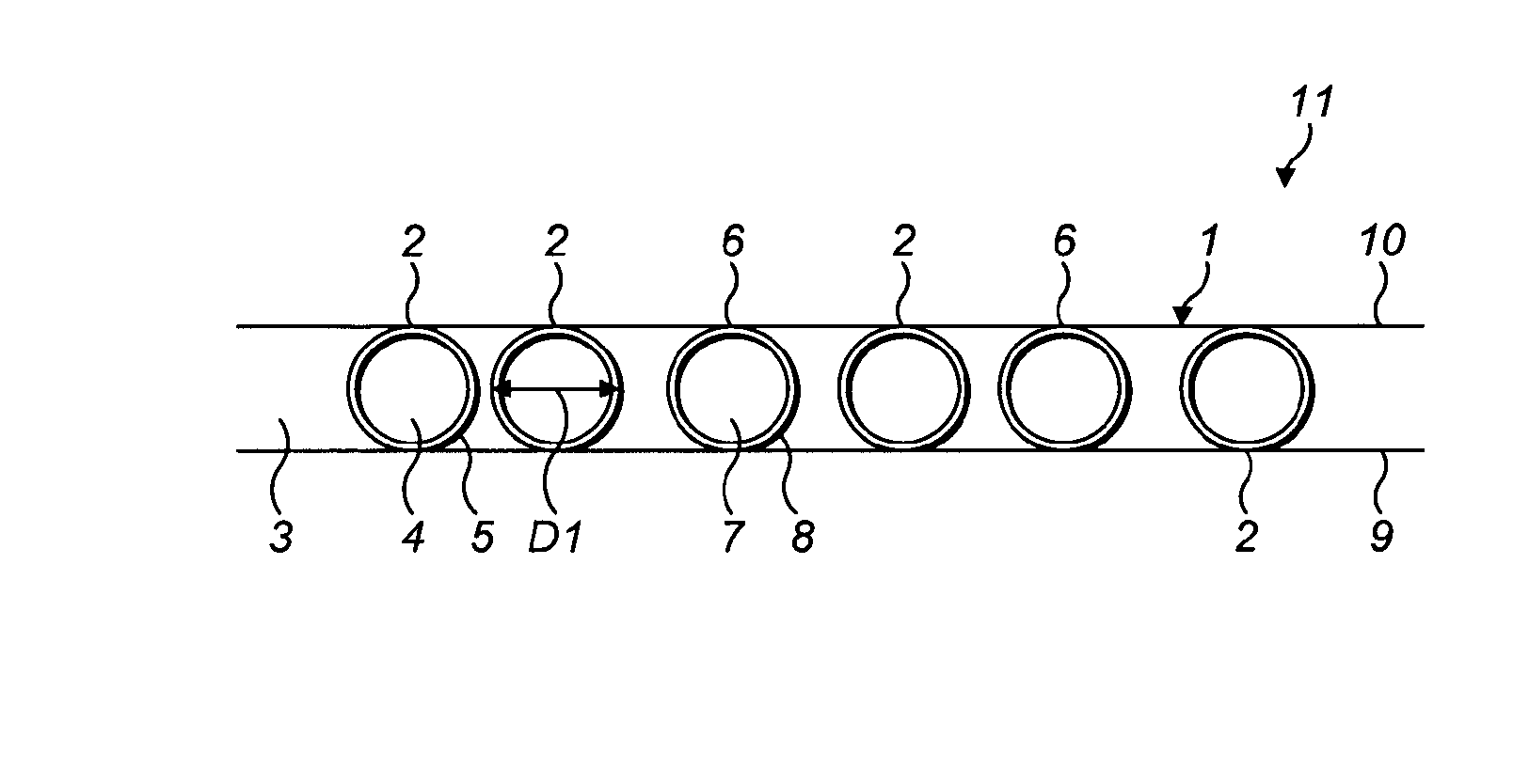
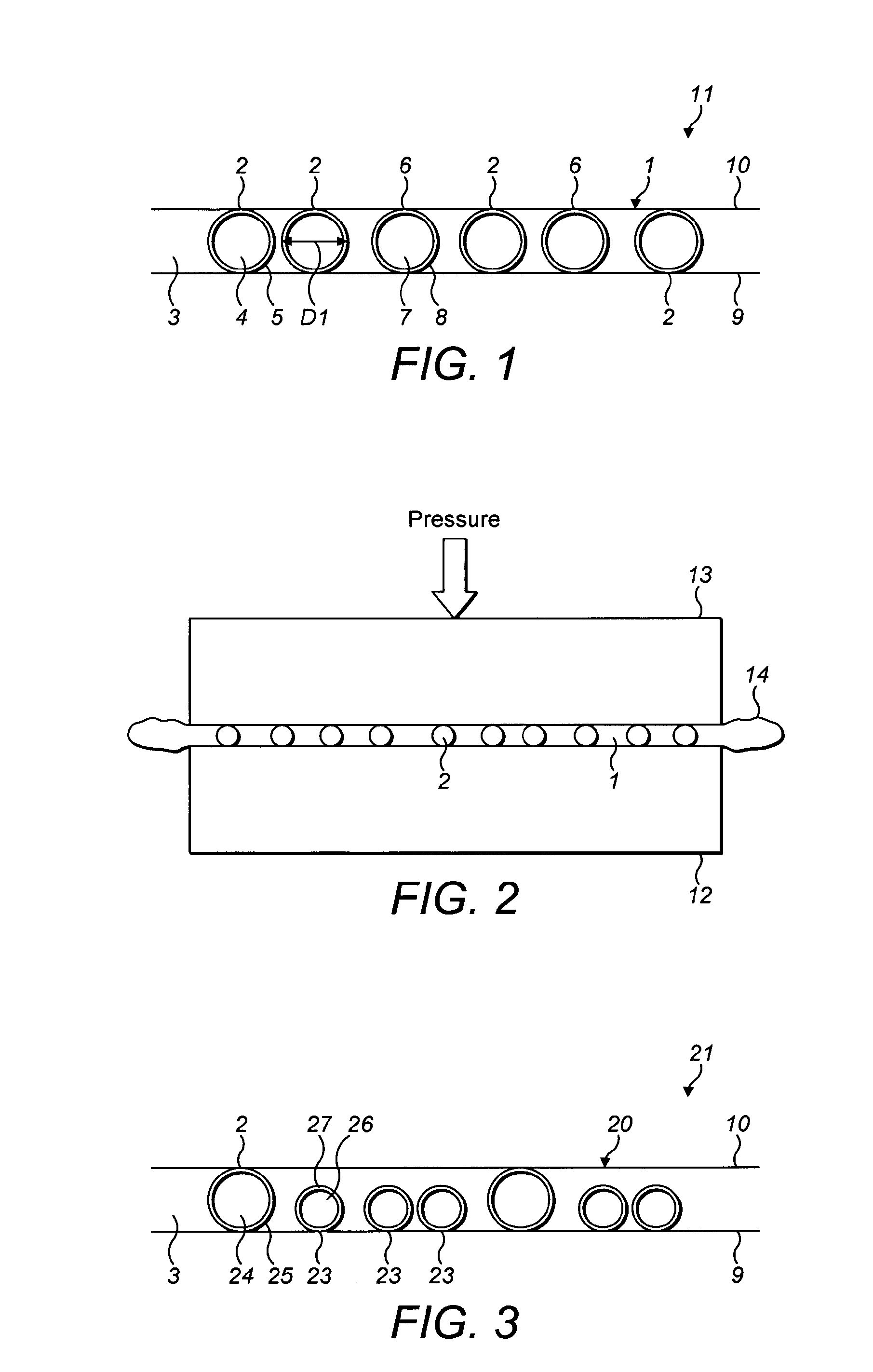
[0023]It will be appreciated that the conductive particles and signal particles are arranged in a planar layer within the conductive adhesive. Ideally, that layer contains a single layer of particles, i.e. the particles a...


PUM

PropertyMeasurementUnit
Lengthaaaaaaaaaa
Fractionaaaaaaaaaa
Fractionaaaaaaaaaa

Abstract

A conductive adhesive, such as an anisotropic conductive adhesive, comprising a population of conductive particles and a population of signal particles in an adhesive; wherein both the conductive particle population and the signal particle population have an average particle diameter of <200 μm with a coefficient of variance of <10%; wherein the signal particles are arranged to provide an indication when they are deformed to a pre-determined height; and wherein the conductive particles are arranged such that they will not fail, e.g. crack or fracture, when deformed to a height larger than or equal to the pre-determined height at which the signal particles are arranged to provide the indication.

Description

[0001]The present invention relates to improvements in conductive adhesives, in particular to improvements that enable determination of when optimum bonding process parameters have been applied during bonding. More specifically, the invention relates to an adhesive having particles that indicate when an optimum deformation of conductive particles has or will be achieved during bonding.BACKGROUND[0002]Conductive adhesives, comprising conductive particles in an adhesive base, are well known. They have many applications but are particularly useful in the manufacture of electronic devices to provide adhesion and electrical connection between components such as in liquid crystal displays (LCDs), LCD screens and driver electronics.[0003]Anisotropic conductive adhesives (ACA) and anisotropic conductive films (ACF) that pass electricity along only one axis provide electrical connection in many critical electronic systems. This approach can replace traditional methods, like soldering, and ca...

Claims


Application Information

Patent Timeline
IPC IPC(8): C09J9/02B32B41/00
CPCC09J9/02B32B2307/202B32B41/00H01R4/04Y10T428/25
Inventor REDFORD, KEITHKRISTIANSEN, HELGE
Owner CONPART
Why Eureka
Try Eureka