
Floor seal for a center knife drive for a sickle of a plant cutting machine

a technology of plant cutting machine and floor seal, which is applied in the direction of mowers, agriculture tools and machines, etc., can solve the problems of accumulated material being lodged between the drive, premature failure of the drive components such as bearings, and crop loss through openings or apertures, etc., to achieve the effect of not failing, effective self-cleaning, and sufficient durability

Active Publication Date: 2015-11-24
BLUE LEAF I P INC
View PDF35 Cites 5 Cited by
  • Summary
  • Abstract
  • Description
  • Claims
  • Application Information

AI Technical Summary

Benefits of technology

The floor seal effectively prevents the accumulation of loose material on the drive components, reducing the risk of overheating and mechanical obstruction, while being durable enough to withstand typical plant cutting conditions and facilitate the operation of flexible cutter bars.

Problems solved by technology

A problem observed with the above center knife drives and other center drives such as pivotally driven drives, is that because of their location in or below the floor or pan, the drives are at least partially contained in a relatively low profile or flat housing or cover, on which loose crop material or residue and other undesirable material such as dust, dirt, and debris, can collect or accumulate.
This is undesirable, as the material, if allowed to accumulate, can insulate the drive to reduce dissipation of heat generated by operation of the drive so as to possibly result in overheating and premature failure of drive components such as bearings.
As another problem, accumulated material can become lodged between the drive and underside of the floor or pan, and can even be compacted into a solid mass, so as to limit or prevent upward movement of the drive.
This can be problematic, for instance, if the drive is used with a cutter bar and sickle that can flex upwardly, and wherein the sickle can be configured in a float mode so as to be movable upwardly toward the floor or pan.
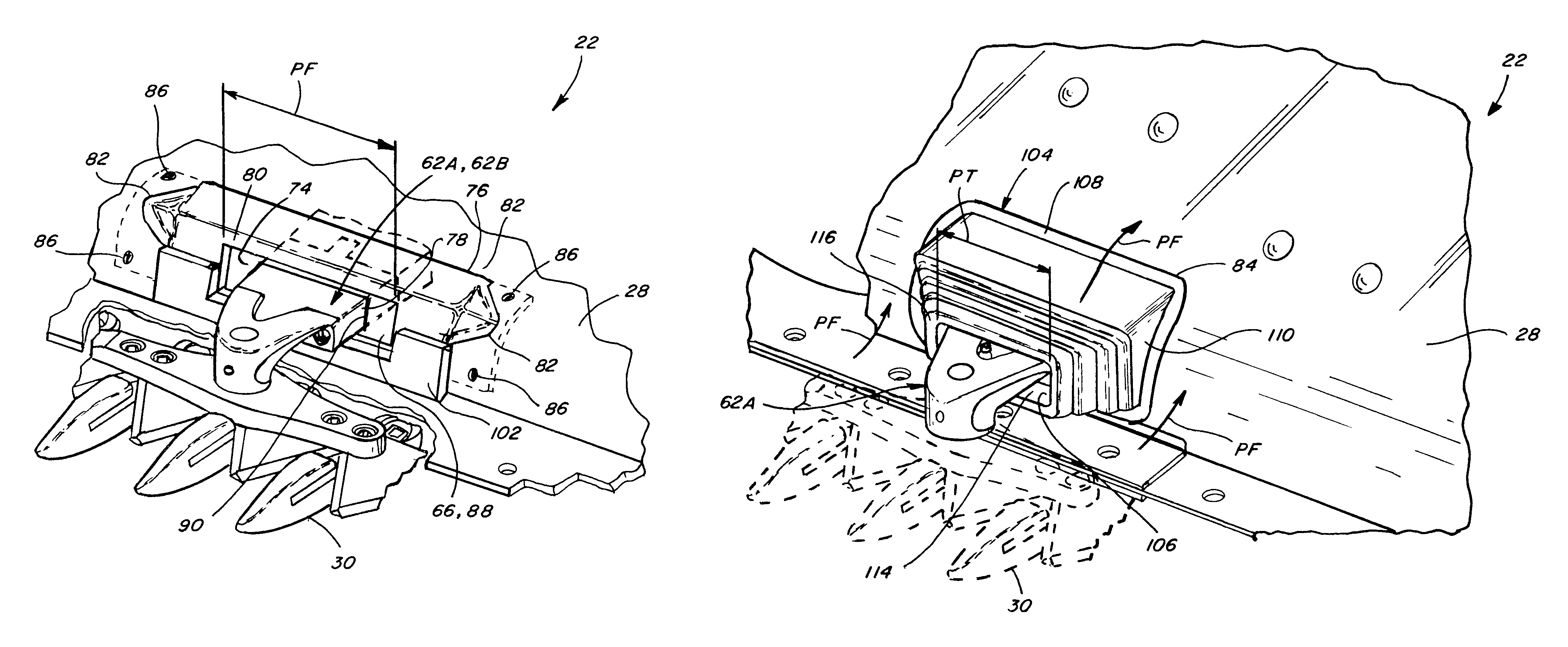
As another possible problem, some crop can be lost through openings or apertures of the floor or pan through which knife arms or other elements connecting with the knife assemblies pass.
This keeps the cut material from collecting on the lever, but does not appear to have utility for preventing or substantially limiting passage of loose material through an opening or aperture in a floor of a plant cutting machine through which a side to side moving lever or knife arm extends.
As still another problem, the openings in a floor of a plant cutting machine through which the knife arms or levers driving a sickle extend, are typically located in a curved or tapered forward edge region of the floor or pan, so as to be at least partially forwardly facing, so as to be directly in the flow of cut crop and other loose material when the machine is moving forward during a plant cutting operation, and so as to be susceptible to having the loose material become trapped or jammed between the sides of the openings and the knife arms or levers which can cause increased stress loads on the drives and resultant wear and damage.

Method used


Image

  • Floor seal for a center knife drive for a sickle of a plant cutting machine
  • Floor seal for a center knife drive for a sickle of a plant cutting machine
  • Floor seal for a center knife drive for a sickle of a plant cutting machine

Examples


Embodiment Construction

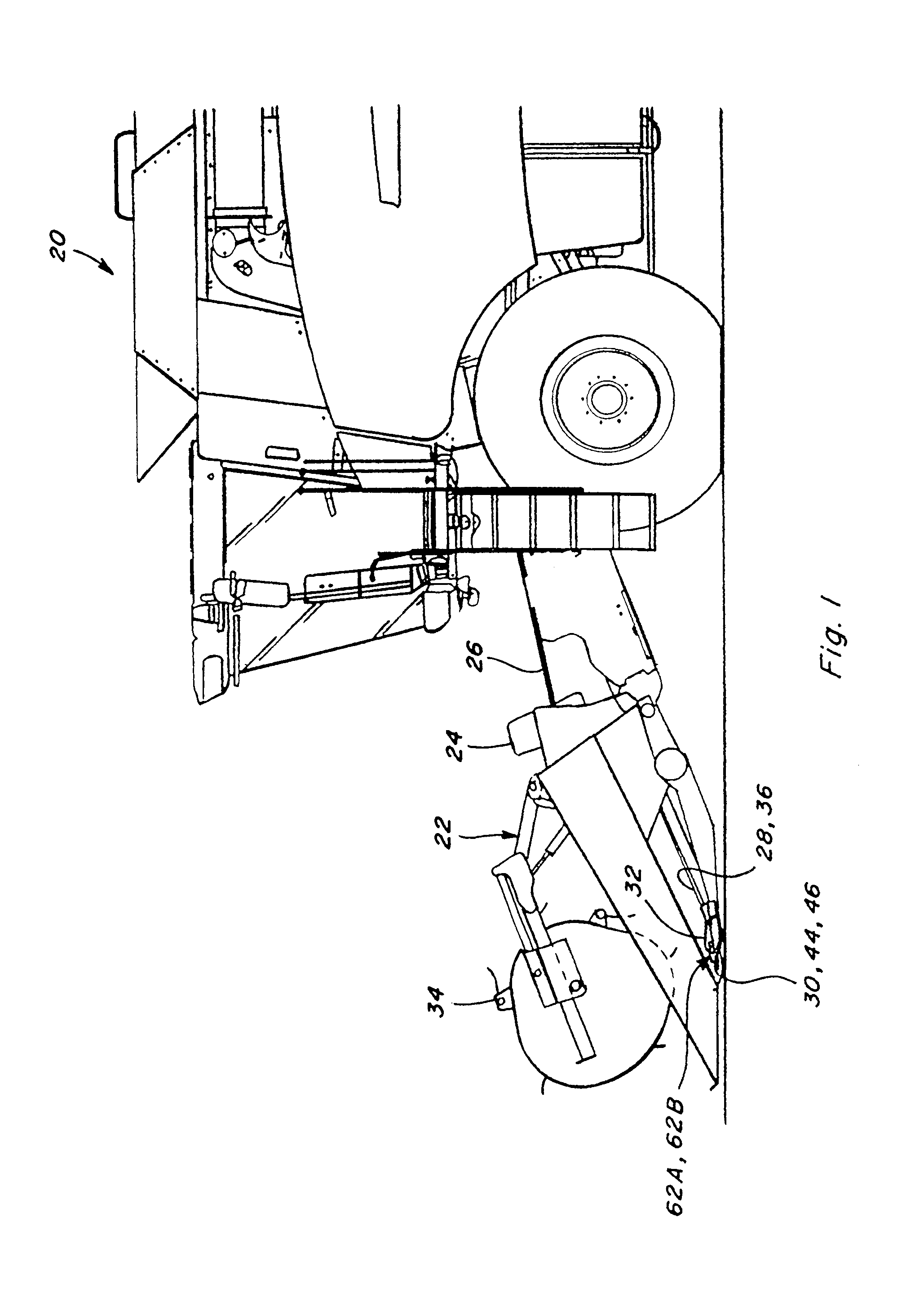
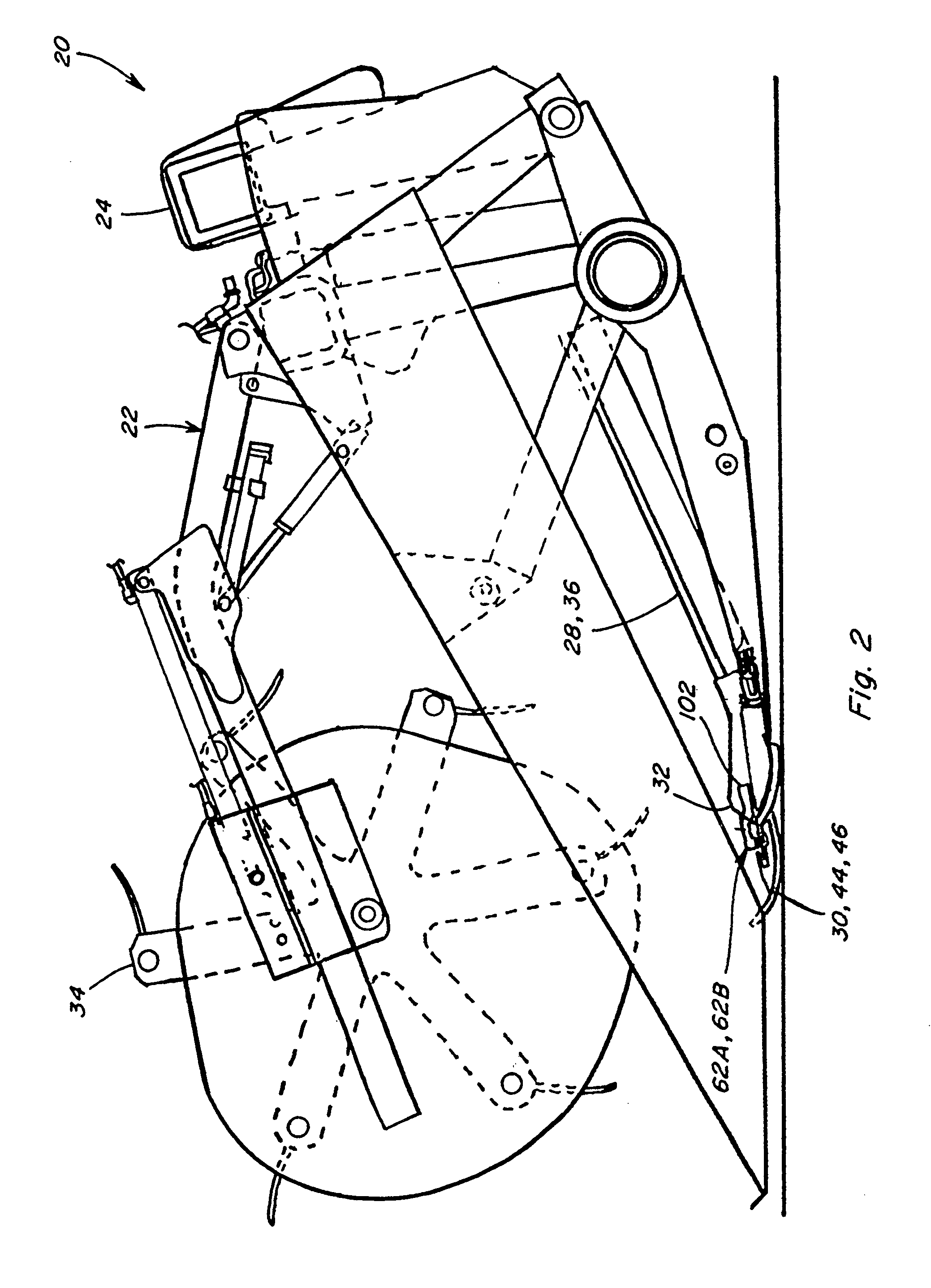
[0029]Turning now to the drawings wherein preferred embodiments of the invention are shown, in FIGS. 1 through 4, a conventional, well known agricultural cutting machine, which is a combine 20, is shown including a header 22. Header 22 is shown supported in the conventional, well-known manner on a forward end 24 of combine 20, and is operable for cutting or severing crops such as, but not limited to, small grains such as wheat and soybeans, and inducting the severed crops into a feeder 26 for conveyance into combine 20 for threshing and cleaning, in the well known manner, as combine 20 moves forwardly over a field.

[0030]Header 22 includes a pan or floor 28 which is supported in desired proximity to the surface of the field during the harvesting operation, and an elongate, sidewardly extending sickle 30 along a forward edge portion 32 of floor 28, sickle 30 being operable for severing the plants or crop for induction into header 22, as will be explained. Header 22 additionally includ...


PUM


Abstract

A floor seal for a forwardly facing opening through a floor of a plant cutting machine through which a knife arm extends for side to side reciprocating movement for driving a sickle of the machine as the machine is moved forwardly for performing a plant cutting operation. The floor seal includes a stationary outer peripheral seal element engaged with a peripheral edge of the floor about the opening and carrying a cover element in covering relation to the opening about the knife arm and defining and bounding a forwardly facing aperture containing the knife arm and an inner peripheral seal element carried in the aperture by the cover element bounding and forming a barrier to entry of loose material or sealed condition about the knife arm and movable side to side therewith relative to the outer seal and cover.

Description

CROSS REFERENCE TO RELATED APPLICATIONS[0001]This application is the US National Stage for International Application No. PCT / US2012 / 042954, filed on Jun. 18, 2012, which itself is related to and claims the benefit of U.S. Provisional Application No. 61 / 520,895, filed Jun. 16, 2011.TECHNICAL FIELD[0002]This invention relates generally to a seal for preventing of entry of loose plant residue and other undesired material through an opening through a floor of a plant cutting machine through which a moving knife arm connecting with a sickle of the machine extends, and more particularly, which includes an element or elements that form a barrier that moves with the knife to prevent or limit entry of crop, plant residue, dirt, dust and other loose material into the opening during side to side movements of the knife arm, to reduce accumulation of the material on a drive or drives of the sickle located in a cavity behind the opening.BACKGROUND ART[0003]The disclosure of U.S. Provisional Appli...

Claims


Application Information

Patent Timeline
Patent Type & Authority Patents(United States)
IPC IPC(8): A01D34/13A01D34/30A01D34/40
CPCA01D34/40A01D34/30A01D34/02
Inventor COOK, JOEL T.
Owner BLUE LEAF I P INC
Learn More