Surface Magnet Type Motor, Fabrication Method Of Surface Magnet Type Motor, And Internal Combustion Engine With Surface Magnet Type Motor

a technology of surface magnets and fabrication methods, applied in the direction of mechanical energy handling, stator/rotor bodies, applying solid insulation, etc., can solve problems such as the possibility of magnet fracture, and achieve the effect of preventing magnet scattering and being durable enough

Active Publication Date: 2008-05-15
TOYOTA JIDOSHA KK
View PDF5 Cites 10 Cited by
  • Summary
  • Abstract
  • Description
  • Claims
  • Application Information

AI Technical Summary

Benefits of technology

[0049]An internal combustion engine including a surface magnet type motor of the present invention is directed to an internal combustion engine including a supercharger with a turbine shaft. The surface magnet type motor having a magnet at the surface of a rotor is employed as a motor for assist of the turbine shaft. The surface magnet type motor includes an anti-scattering tube formed in a cylindrical configuration longer in length than the magnet mounted at the rotorin an axial direction, having the magnet press-fitted therein for preventing scattering of the magnet. The surface magnet type motor is provided with a stress alleviation portion for alleviating stress generated at an end of the magnet press-fitted into the anti-scattering tube. The surface magnet type motor is provided coaxially with the turbine shaft.
[0050]According to the internal combustion engine of the present invention, the surface magnet type motor for alleviating stress generated at the end of the magnet is arranged coaxially with the turbine shaft for assist of the turbine shaft. Since the surface magnet type motor is under a state in which the stress on the magnet is alleviated, the surface magnet type motor is sufficiently durable even if great centrifugal force is applied by the rotation together with the turbine shaft that rotates at high speed. There can be provided an internal combustion engine with a supercharger including a motor for assist that can be arranged coaxially with a turbine shaft that rotates at high speed.

Problems solved by technology

However, increase of the press-fit margin induces the possibility of the magnet being fractured during the press-fitting stage into the anti-scattering tube.
Even if the event of fracture does not occur at the time of assembly, such stress on the magnet may result in fracture during operation of the surface magnet type motor by the effect of the centrifugal force.

Method used


Image

  • Surface Magnet Type Motor, Fabrication Method Of Surface Magnet Type Motor, And Internal Combustion Engine With Surface Magnet Type Motor
  • Surface Magnet Type Motor, Fabrication Method Of Surface Magnet Type Motor, And Internal Combustion Engine With Surface Magnet Type Motor
  • Surface Magnet Type Motor, Fabrication Method Of Surface Magnet Type Motor, And Internal Combustion Engine With Surface Magnet Type Motor

Examples


first embodiment

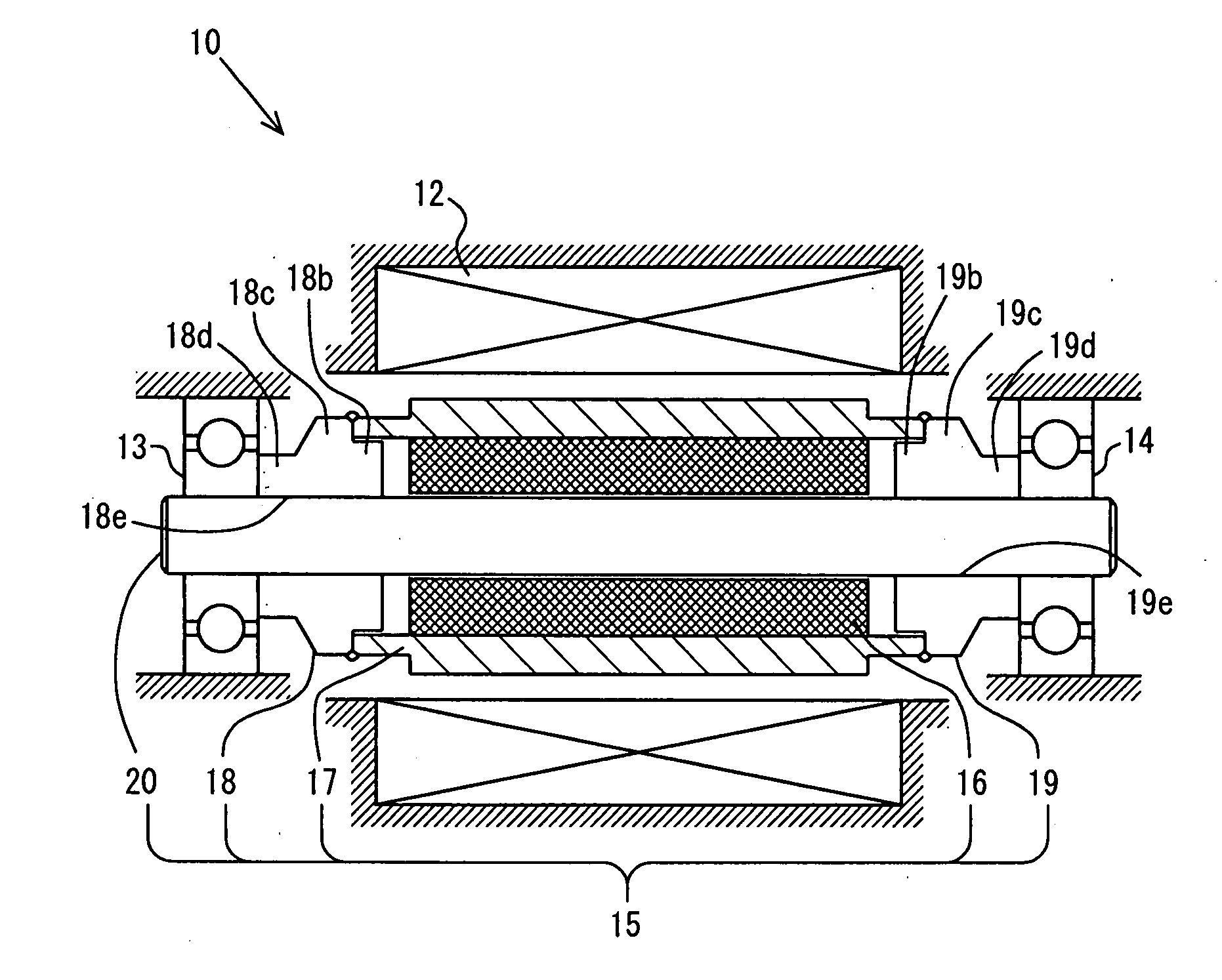
[0084]Rotational shaft 20 of the assembled rotor 15 has bearings 13 and 14 attached. For bearings 13 and 14, a ball bearing having low rotation resistance is employed to take a structure that can withstand even high speed rotation. By mounting rotor 15 with bearings 13 and 14 attached in a housing of motor 10 including stator 12, electric motor 10 is implemented. The current flow to the coil of stator 12 is supplied from an electric circuit (refer to FIG. 18).[0085]A-1. First Embodiment of Anti-Scattering Tube:

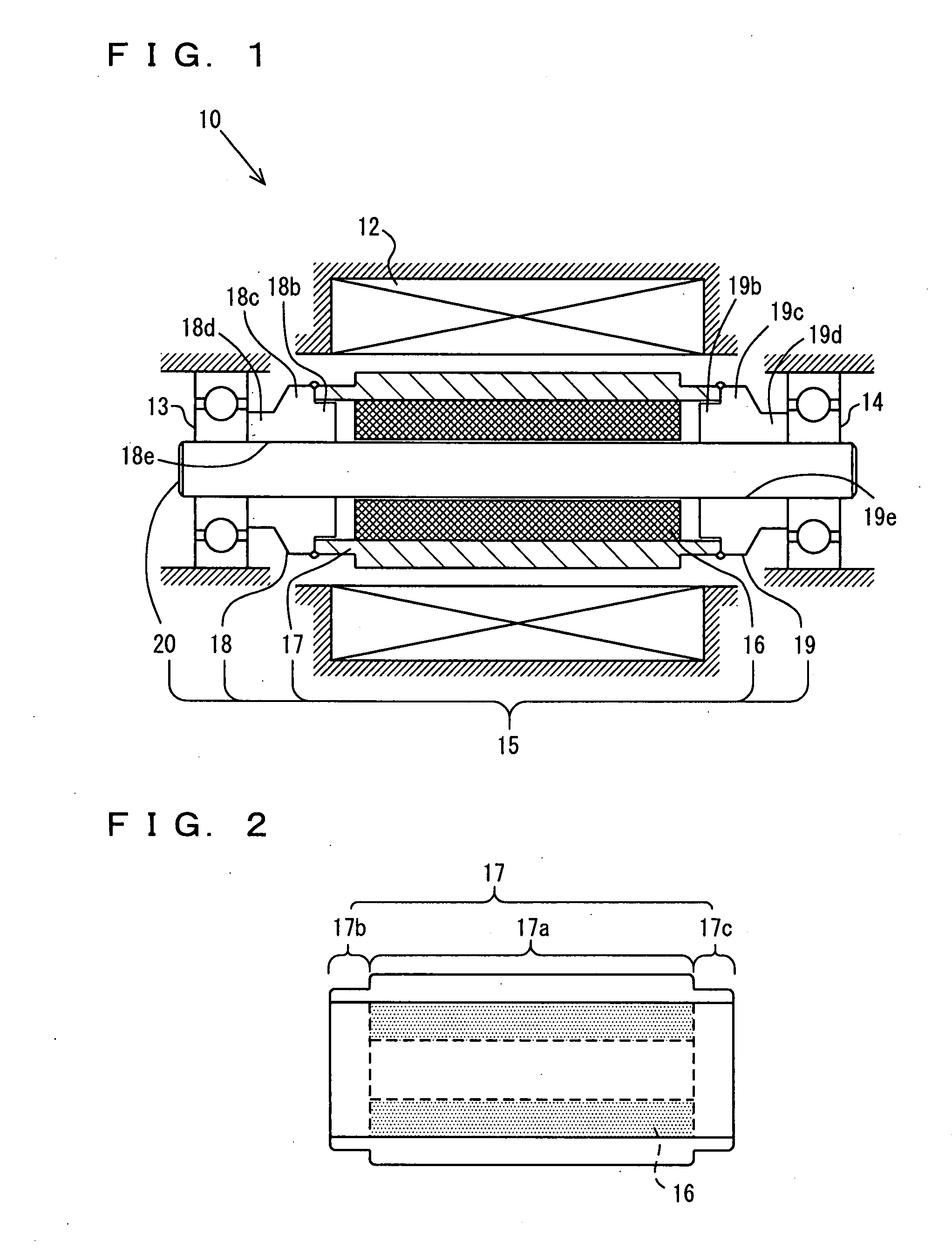
[0086]FIG. 2 is a sectional view of a structure of anti-scattering tube 17 of the first embodiment into which magnet 16 is press-fitted. As shown in the drawing, anti-scattering tube 17 made of titanium is formed in a step-graded cylindrical configuration longer in length than magnet 16. Magnet 16 is located in the proximity of approximately the center of the step-graded cylindrical configuration. This anti-scattering tube 17 is mainly formed of three portions, i.e. a cylinder...

second embodiment

[0092]FIG. 4 shows an example of an anti-scattering tube including a projection portion of low rigidity. As shown in the drawing, an anti-scattering tube 27 has a cylindrical configuration substantially similar to that of anti-scattering tube 17 of FIG. 2, and differs only in the configuration of projection portions 27b and 27c protruding from the end face of press-fitted magnet 16. Projections 27b and 27c of anti-scattering tube 27 has a groove corresponding to a notch of a predetermined width and predetermined depth over the entire perimeter. By providing such notches, similar advantages can be provided even with projection portions 27b and 27c of low rigidity. Furthermore, projection portions 27b and 27c of low rigidity can be formed by a relatively simple process.[0093]A-2. Second Embodiment of Anti-Scattering Tube:

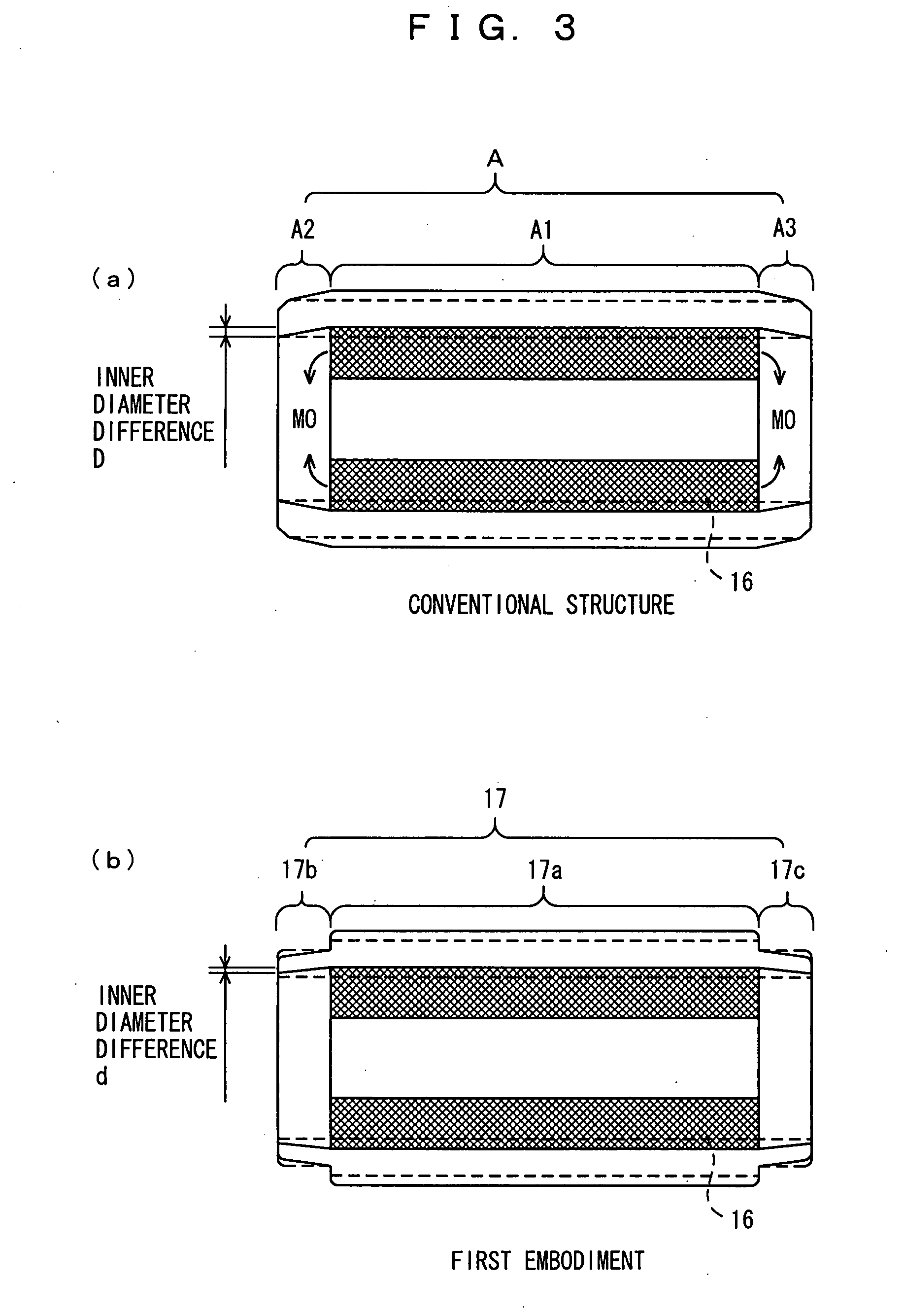
[0094]The first embodiment is directed to suppressing the inner diameter difference by forming projection portions 17b and 17c in a configuration of low rigidity. How...

third embodiment

[0111]Salient 57a provided only on the part of anti-scattering tube 57 may be provided only on the part of assembly flange 48, as shown in FIG. 12. In this case, a salient 48a is provided at assembly flange 48, as shown in the drawing. It is not necessary to provide a particular configuration for the anti-scattering tube, as compared to the structure shown in FIG. 10.[0112]B-3. Third Embodiment of Contact Portion Structure:

[0113]FIG. 13 is a partial sectional view of a structure of a contact portion of the assembly flange and anti-scattering tube according to a third embodiment. Although only the bearing 13 side is indicated as the contact portion structure in FIG. 13, a contact portion structure symmetric to the bearing 13 side is provided at the bearing 14 side, likewise FIG. 10.

[0114]As shown in the drawing, the contact portion of anti-scattering tube 67 includes a tapered portion 67a having the inner diameter increased in the direction from the end face of magnet 16 to the end f...


PUM

PropertyMeasurementUnit
outer circumferenceaaaaaaaaaa
lengthaaaaaaaaaa
stressaaaaaaaaaa

Abstract

A surface magnet type motor having a magnet at a surface of a rotor includes an anti-scattering tube formed in a cylindrical configuration longer in length than the magnet of the rotor in the axial direction, having the magnet press-fitted inside to prevent scattering of the magnet. A stress alleviation portion is provided to alleviate stress generated at an end of the magnet press-fitted into the anti-scattering tube.

Description

TECHNICAL FIELD[0001]The present invention relates to a surface magnet type motor employing a magnet for the rotor, particularly to an anti-scattering tube for preventing scattering of the magnet.BACKGROUND ART[0002]Conventionally, there is known a surface magnet type motor including a rotor having a magnet arranged at the outer circumferential surface of the rotational shaft. This type of motor is provided with a non-magnetic anti-scattering tube at the circumference of the magnet to prevent fracture and scattering of the magnet caused by the centrifugal force when the rotor rotates at high speed.[0003]The anti-scattering tube of the motor is generally fixed by press-fitting the magnet into the inner cylinder of the anti-scattering tube. Accordingly, the magnet is firmly maintained with force to prevent fracture and scattering of the magnet caused by centrifugal force (for example, refer to Japanese Patent Laying-Open Nos. 2001-025193 and 2001-218403).[0004]In order to realize usag...

Claims


Application Information

Patent Timeline
Patent Type & Authority Applications(United States)
IPC IPC(8): H02K5/16
CPCH02K1/2733Y10T29/49012H02K15/03
Inventor MAEDA, TOMOYUKI
Owner TOYOTA JIDOSHA KK
Why Eureka
Try Eureka