Wind turbine component comprising radar-absorbing material

a radar-absorbing material and wind turbine technology, applied in the direction of wind turbines with parallel air flow, liquid fuel engine components, non-positive displacement fluid engines, etc., can solve the problems of reducing ram performance, and achieve the effect of facilitating film application

Inactive Publication Date: 2013-10-24
VESTAS WIND SYST AS
View PDF11 Cites 10 Cited by
  • Summary
  • Abstract
  • Description
  • Claims
  • Application Information

AI Technical Summary

Benefits of technology

[0011]If the component is made from multiple elements that are joined together, for example upper and lower blade shells, the elements may be joined prior to applying the CA elements. Hence, the step of making the component may include joining two elements together to form at least part of the component. The step of modifying the component may include applying the CA elements to a region of the surface that bridges an interface between the two elements. Providing the CA elements after the elements have been joined enables the CA elements to be applied as a repeating pattern that is not disrupted at the join between the elements.
[0016]The method may include applying a protective layer over the CA elements to protect the CA elements from environmental conditions. For example, the method may involve painting over the CA elements. The gel coat may be partially ground off before the CA elements are applied. Grinding the gel coat provides a keying surface to ensure a strong bond between the paint and the gel coat. Alternatively, a film may be provided over the CA elements. Suitable films include paint-replacement films, which are commonly used in the automotive industry. Alternately, the CA elements may be sufficiently durable to withstand environmental conditions without needing to be covered.
[0020]Conveniently, the film may have an adhesive surface to facilitate application of the film to the surface of the component. The adhesive may be a heat-activated adhesive or a pressure-sensitive adhesive. The CA elements may be carried on the adhesive surface of the film. This is advantageous because the film then covers the CA elements on the surface of the component and provides protection against environmental conditions. Alternatively, the CA elements may be provided on the opposite surface of the film. In this configuration the film would not protect the CA elements from environmental conditions, and so the CA elements would need to be intrinsically durable or they could be covered by a protective layer such as a paint layer or another film layer.
[0023]Expressed in apparatus terms, the present invention provides a wind turbine component of composite construction and having enhanced radar-absorbing properties, wherein circuit analogue elements are provided on an outer surface of the component.

Problems solved by technology

This is because the repeating pattern of the CA elements is inevitably disrupted at the join, which can result in reduced RAM performance.

Method used


Image

  • Wind turbine component comprising radar-absorbing material
  • Wind turbine component comprising radar-absorbing material
  • Wind turbine component comprising radar-absorbing material

Examples


Embodiment Construction

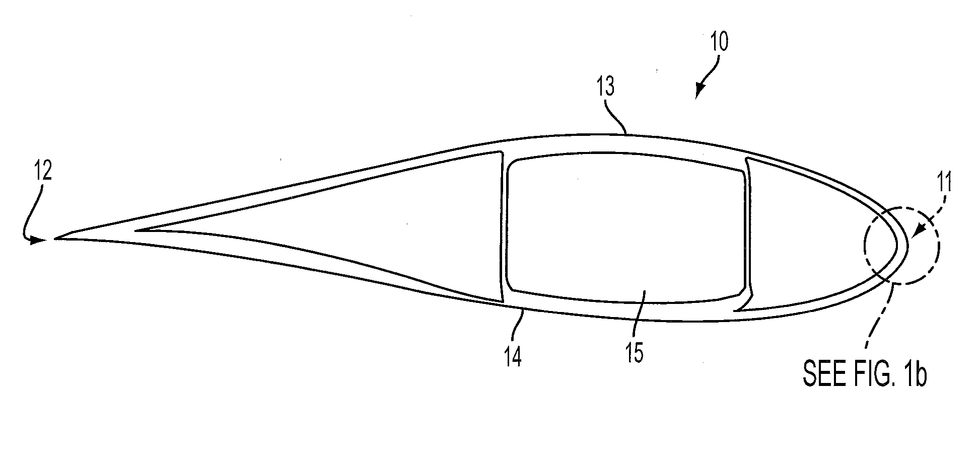
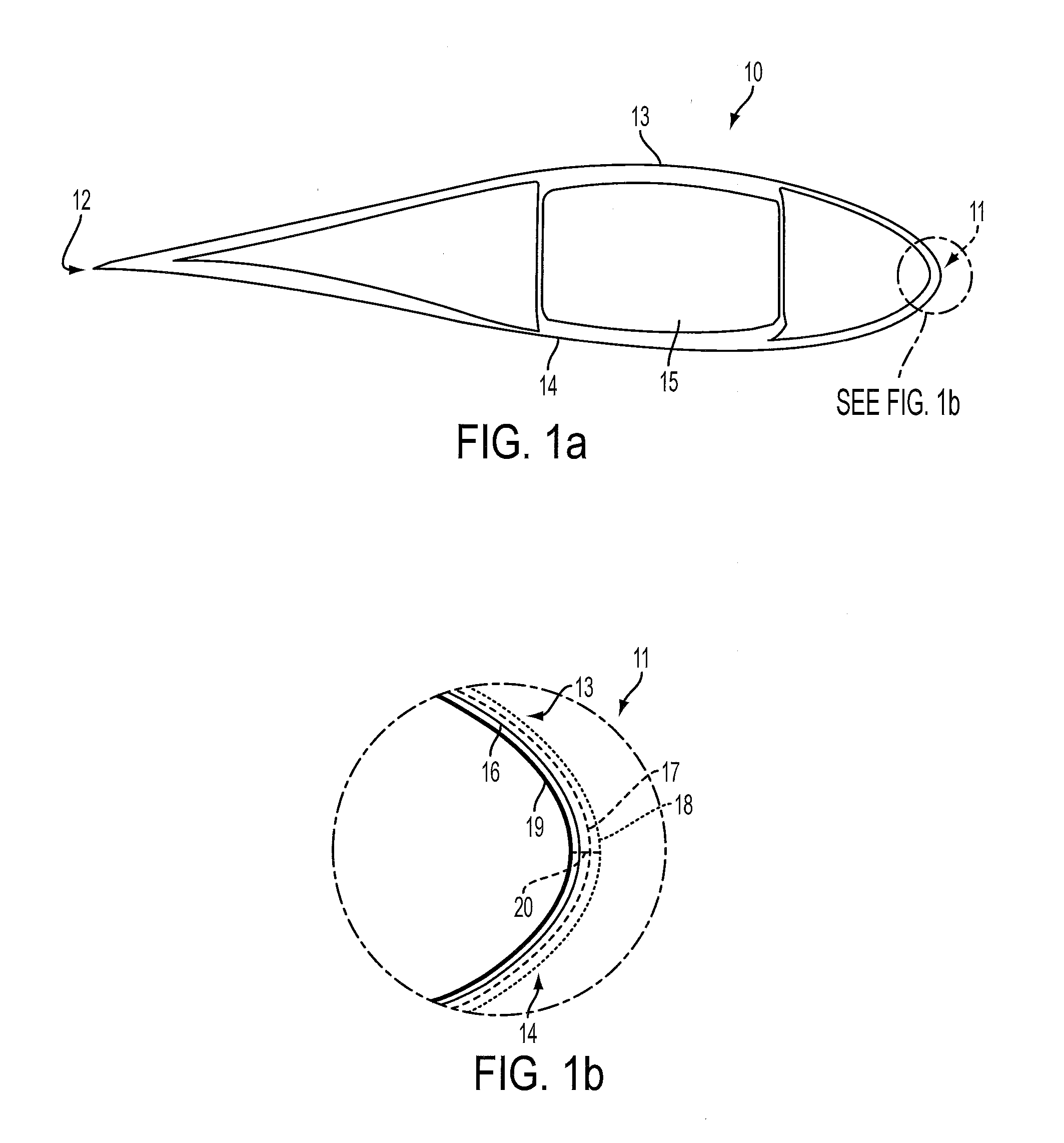
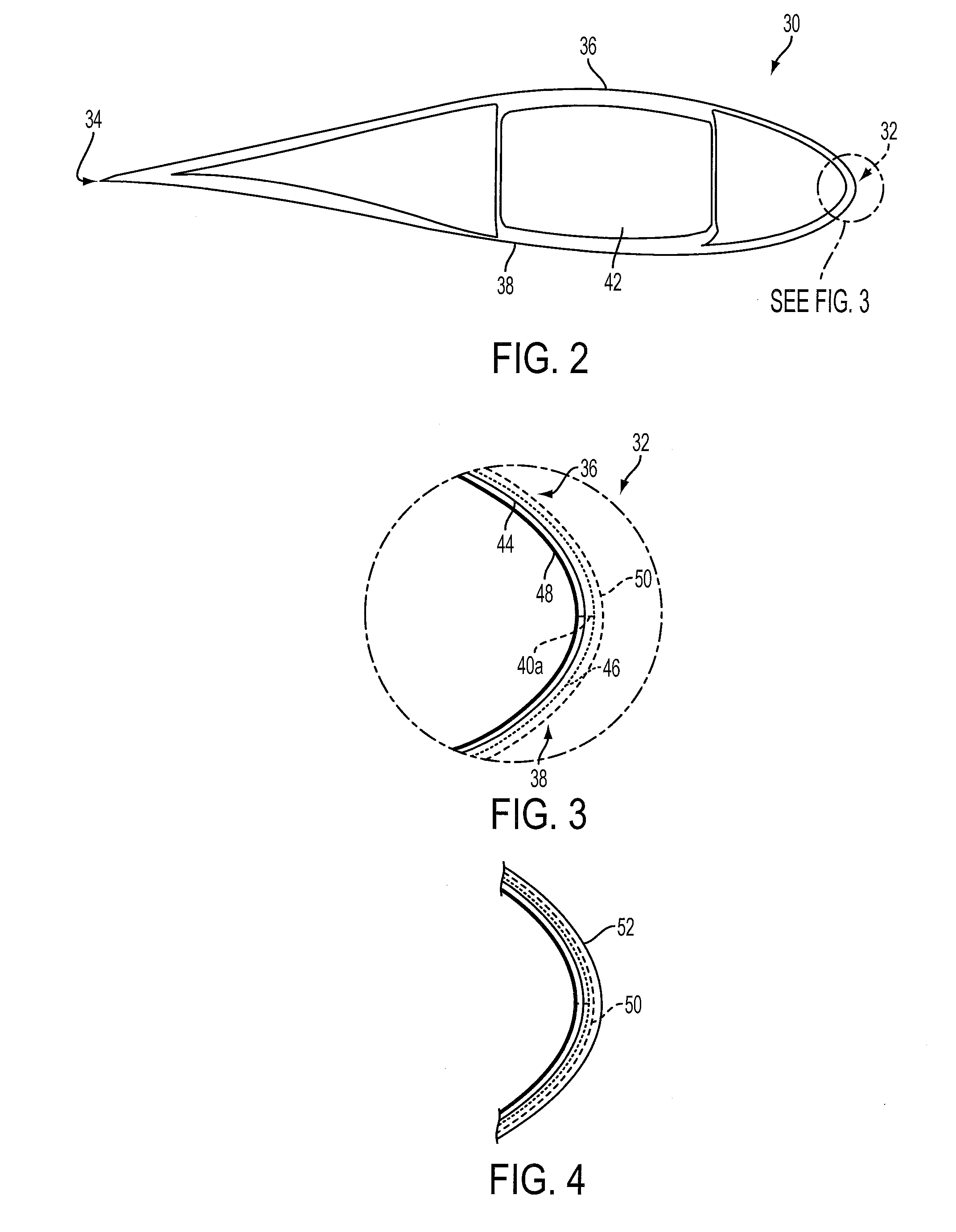
[0037]FIG. 2 is a cross-section through an aerofoil part of a wind turbine blade 30 in accordance with the present invention. The blade 30 extends between a leading edge 32 and a trailing edge 34, and is constructed from two aerodynamic shells, an upper shell 36 and a lower shell 38. The shells 36, 38 are joined together at join lines or seams that extend along the leading and trailing edges 32, 34 respectively. The seam 40a at the leading edge 32 can be seen in FIG. 3. The shells 36, 38 are supported by a tubular structural spar 42 formed from glass fibre and carbon fibre.

[0038]FIG. 3 is an enlarged schematic view of the leading edge 32 of the blade 30, in which the various layers comprising the shells 36, 38 can be seen. For ease of illustration the layers are shown separated, but in reality adjacent layers would abut. Each shell has a GFRP skin 44 formed from one or more layers of glass-fibre fabric within a hardened epoxy resin matrix. A gel coat 46 covers the outer surface of t...


PUM

PropertyMeasurementUnit
thickaaaaaaaaaa
adhesiveaaaaaaaaaa
radar reflectivityaaaaaaaaaa

Abstract

A method of making a wind turbine component of composite construction with enhanced radar absorbing properties is described. The method comprises making the component and then modifying the component by applying circuit analogue elements to a surface of the component.

Description

FIELD OF THE INVENTION[0001]The present invention relates to composite structures such as wind turbine blades that include radar-absorbing material.BACKGROUND[0002]It is known to incorporate radar-absorbing material (RAM) into composite structures such as wind turbine blades. This is done to reduce the radar reflectivity of the blades so that they do not interfere with radar systems such as air traffic control systems or marine radar systems.[0003]Many radar-absorbing materials are based upon the Salisbury Screen, which comprises three layers: a lossless dielectric layer sandwiched between a reflector layer or ‘ground plane’ and an impedance layer or ‘lossy screen’. The lossless dielectric is of a precise thickness equal to a quarter of the wavelength of the radar wave to be absorbed; the ground plane comprises a layer of highly reflective conductive material such as metal or carbon; and the lossy screen is generally a thin resistive layer.[0004]Circuit analogue (CA) RAM technology ...

Claims


Application Information

Patent Timeline
Patent Type & Authority Applications(United States)
IPC IPC(8): F01D5/14
CPCF01D5/147F03D1/0633F03D1/065F03D13/20F05B2230/60F05B2260/99H01Q17/005Y02E10/72Y02E10/728Y02P70/50Y10T29/49336F03D80/00F41H3/00H01Q17/00
Inventor APPLETON, STEVE
Owner VESTAS WIND SYST AS
Why Eureka
Try Eureka