System And Method For Analysing Vapour Pressure

a technology of vapour pressure and apparatus, which is applied in the direction of optical conversion of sensor output, material testing goods, instruments, etc., can solve the problems of delay in obtaining data, and achieve the effect of not to fail, easy upgrades of sensors, and robust construction

Inactive Publication Date: 2016-02-11
ICON SCI
View PDF4 Cites 8 Cited by
  • Summary
  • Abstract
  • Description
  • Claims
  • Application Information

AI Technical Summary

Benefits of technology

[0026]Preferably the apparatus comprises a device for monitoring the temperature of the chamber and a temperature control apparatus to heat or cool the chamber. It may be that the temperature control apparatus comprises a heater, for example a cartridge heater. It may be that the temperature control apparatus comprises a cooler, for example a Peltier cooler. Preferably the temperature control apparatus comprises a cooler and a heater. In some embodiments the temperature control apparatus may be a combined heater and cooler. It will be appreciated that a vapour pressure measurement is made at a temperature. Therefore it is desirable to control the temperature of the chamber. That may be achieved by controlling the environment around the apparatus, for example by immersing the apparatus in a water or oil bath, but such an approach may not be desirable for electrical or optical reasons. By using a device, such as a thermocouple or resistance temperature detector (RTD), to monitor the temperature of the chamber and providing a heater, such as a cartridge heater, and a cooler, such as a Peltier cooler, to heat or cool the chamber, the temperature of the chamber can be controlled independently of the environment. That may be particularly advantageous where the apparatus is used online in the field as the environment in the field may vary considerably more than if, say, the apparatus was used in a laboratory. Preferably the device for monitoring the temperature of the chamber is located within the moveable element. Preferably the apparatus comprises a pressure sensor to measure the pressure in the chamber, wherein the pressure sensor is located within the moveable element. There may be electronics associated with the pressure sensor, the electronics being located within the moveable element. Locating the electronics and sensors within the moveable element may allow them to be in a more stable temperature environment and may allow for easy upgrades of the sensors by substitution of the moveable element.
[0027]Advantageously the apparatus is contained within an explosion-proof housing, for example an explosion-proof box. The skilled person will appreciate that an explosion-proof housing is one that prevents potential ignition sources, such as sparks, flames or explosions, within the housing escaping to the outside environment. For example, the housing may have a robust construction so as not to fail in the event of an explosion within the housing and inlets and outlets to the housing may be provided with breathing and draining devices, or flame arrestors, that prevent a flame from exiting the housing. In that way the apparatus can be used in areas with a potentially explosive atmosphere such as oil refineries to provide online monitoring of a process. If the displacement sensor is a non-contact, for example laser, device with good reliability, the explosion proof housing may need opening less frequently for maintenance. It will be appreciated that opening the explosion-proof housing may require special precautions so as not to ignite a potentially explosive atmosphere surrounding the housing.

Problems solved by technology

The measurements can be carried out by taking a sample to a laboratory but doing so results in a delay in obtaining the data.
However, refineries often include zones with potentially explosive atmospheres so online measurements need to be safe for use in such zones.

Method used


Image

  • System And Method For Analysing Vapour Pressure
  • System And Method For Analysing Vapour Pressure
  • System And Method For Analysing Vapour Pressure

Examples


Embodiment Construction

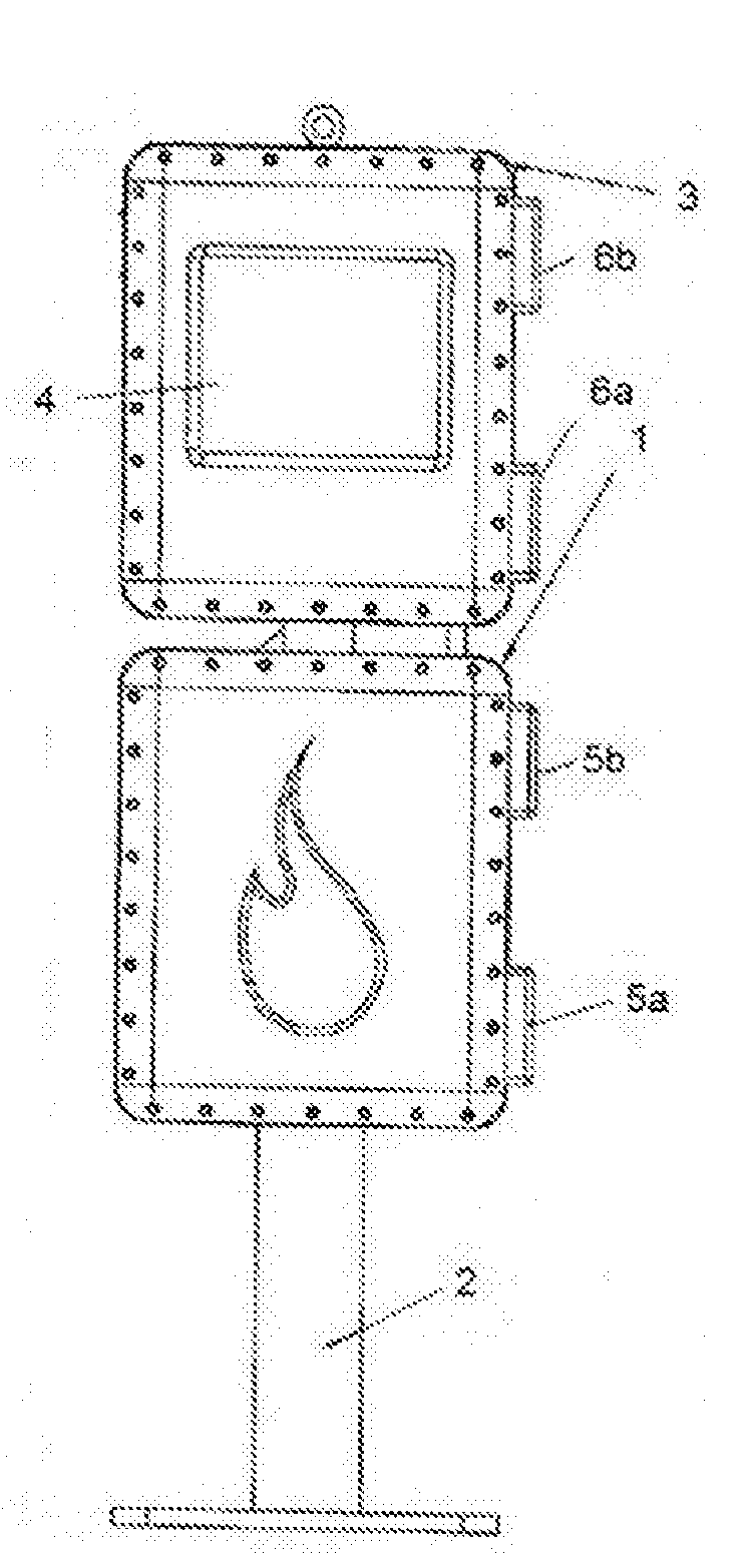
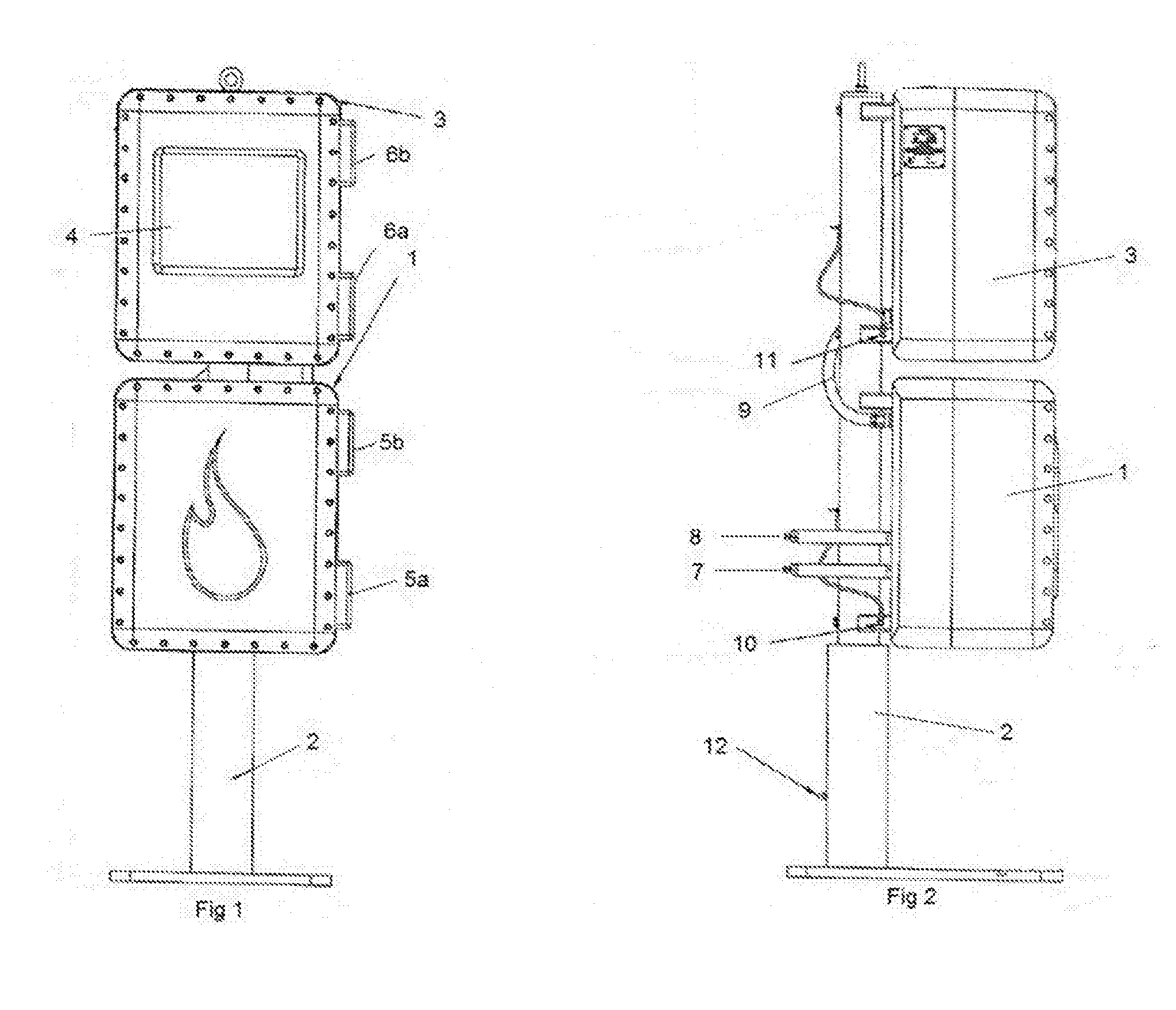
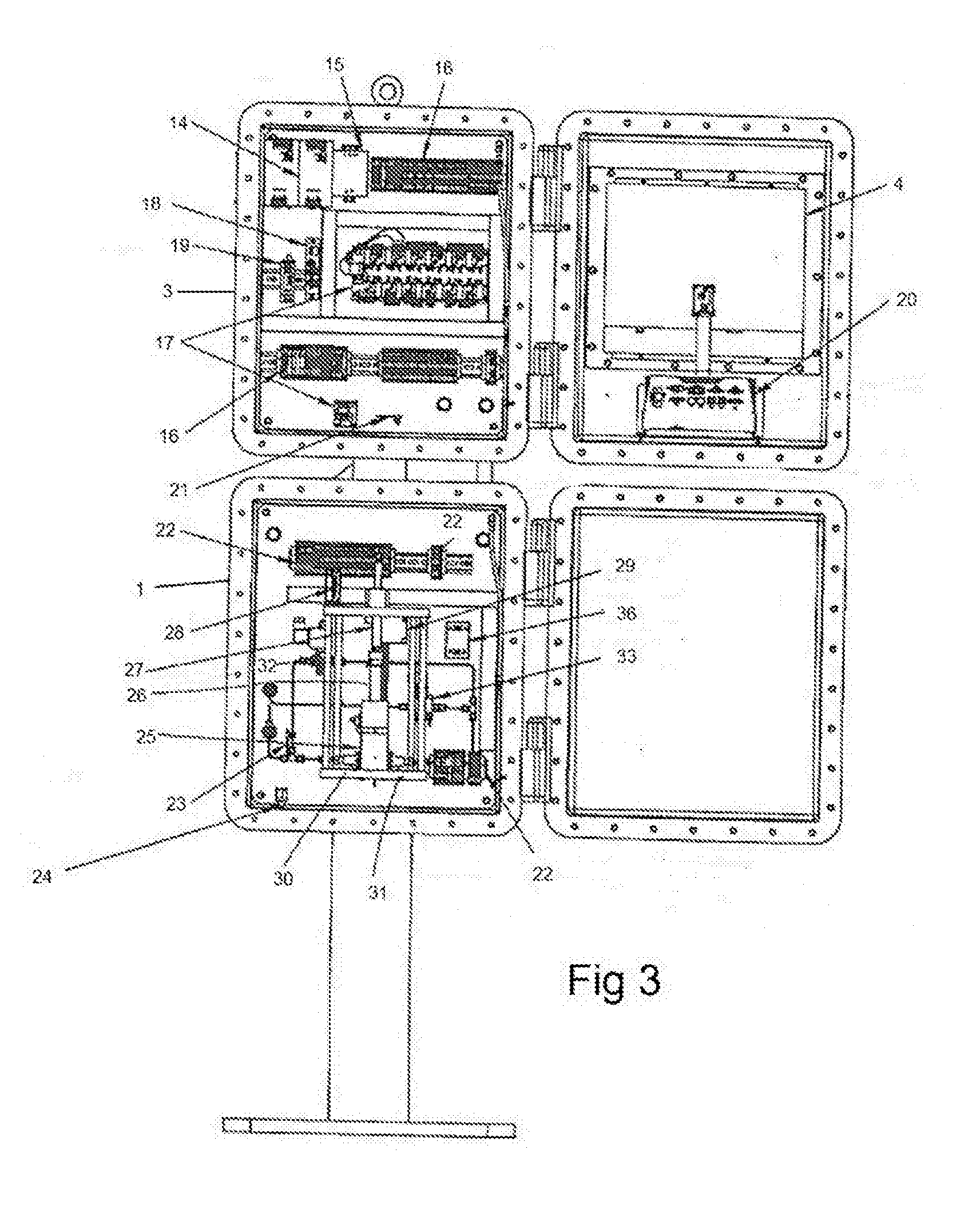
[0095]In FIG. 1 a vapour pressure analyser is contained within an explosion-proof box 1. The box 1 is mounted on a stand 2 on which there is mounted a second explosion-proof box 3. The box 3 is mounted above the box 1 with a 40 mm separation between the boxes. On the front of the box 3 there is a touch screen 4. The fronts of boxes 1 and 3 are mounted on hinges 5a,b and 6a,b respectively so that the fronts of the boxes 1 and 3 can pivot through 180° to open the boxes 1 and 3.

[0096]In FIG. 2 breathing and draining devices 7 and 8 are mounted on the back of box 1. Communication cable 9 connects boxes 1 and 3 so as to allow power and data transfer between the various electronic devices within the boxes 1 and 3. Boxes 1 and 3 have external enclosure earth bolts 10 and 11 mounted on them to earth the boxes 1 and 3. Earth stud 12 is mounted on frame 2.

[0097]In FIGS. 3 and 4 box 1 and box 3 are open. In FIG. 3, box 3 contains power supply units 14 and mains power filter 15. The box 3 also ...


PUM

PropertyMeasurementUnit
temperaturesaaaaaaaaaa
temperatureaaaaaaaaaa

Abstract

An apparatus for measuring the vapour pressure of a liquid hydrocarbon sample is disclosed. The apparatus comprises a sealed chamber (25) for receiving the sample. The chamber (25) is at least partially defined by a moveable element (26) such that moving the moveable element (26) alters the volume of the chamber (25). The apparatus comprises a displacement sensor (29) configured to measure a displacement of the movable element (26).

Description

FIELD OF THE INVENTION[0001]The present invention concerns apparatus and methods for measuring the vapour pressure of hydrocarbons. In particular, but not exclusively, the invention concerns apparatus and methods for measuring the vapour pressure of hydrocarbons online in chemical plants or refineries.BACKGROUND OF THE INVENTION[0002]Vapour pressure is a well-known parameter related to the volatility of a substance. The vapour pressure is the pressure of a gaseous substance in equilibrium with the condensed substance in a closed system at a fixed temperature.[0003]Vapour pressure can be measured using many standard methods. Examples of standard methods for measuring hydrocarbon vapour pressures include ASTM D6377: Determination of Vapour Pressure of Crude Oil: VPCRx (Expansion Method); ASTM D6378: Determination of Vapour Pressure (VPX) of Petroleum products, Hydrocarbons, and Hydrocarbon-Oxygenate mixtures (Triple Expansion Method); and ASTM D6897: Vapour Pressure of Liquefied Petro...

Claims


Application Information

Patent Timeline
Patent Type & Authority Applications(United States)
IPC IPC(8): G01D5/28G01L7/16G01N33/24
CPCG01L7/16G01N33/24G01D5/28G01N7/14B60W30/14B60W30/143B60K23/00
Inventor FOGARTY, KEVINHOPE, DAVIDTHOMPSON, DAVEBIRCHMORE, BOB
Owner ICON SCI
Why Eureka
Try Eureka