Control device switching system

Active Publication Date: 2015-10-22
MITSUBISHI ELECTRIC CORP
View PDF5 Cites 5 Cited by
  • Summary
  • Abstract
  • Description
  • Claims
  • Application Information

AI Technical Summary

Benefits of technology

The invention is about a control device switching system that can prevent network failures and abnormal vehicle behaviors. The system includes multiple control devices connected to a common communication line. A decision is made whether a control device should switch off or sleep based on its capabilities to handle data transmission. The system allows for the data transmission process to be taken over by another device if the current device fails. This ensures reliable data transmission and prevents network failures or vehicle abnormalities.

Problems solved by technology

However, as the number of the control devices incorporated in a vehicle increases in recent years, the amount of electric power consumed by the control devices tends to increase accordingly.
When the amount of power consumption increases, the amount of power to be generated by the alternator and the like also increases, leading to poorer fuel economy of the vehicle.
However, in a network provided with an abnormality sensing device, a control device that does not perform data reception for a predetermined duration may be regarded as having a trouble, and an abnormality process may be started therefor.
However, when the transmission-reception control device is out of order or is under a high processing load, or when it is executing other important processes, an event occurs that the transmission-reception control device cannot substitute data transmission.
This event is detected as a network failure by the abnormality sensing device.
Moreover, if the transmission-reception control device is forced to take over the data transmission to be originally performed by the target control device while the transmission-reception control device is under a high processing load or performing an important process, the transmission-reception control device loses its real-timeness, resulting in a failure in the behaviors of the vehicle.

Method used


Image

  • Control device switching system
  • Control device switching system
  • Control device switching system

Examples


first preferred embodiment

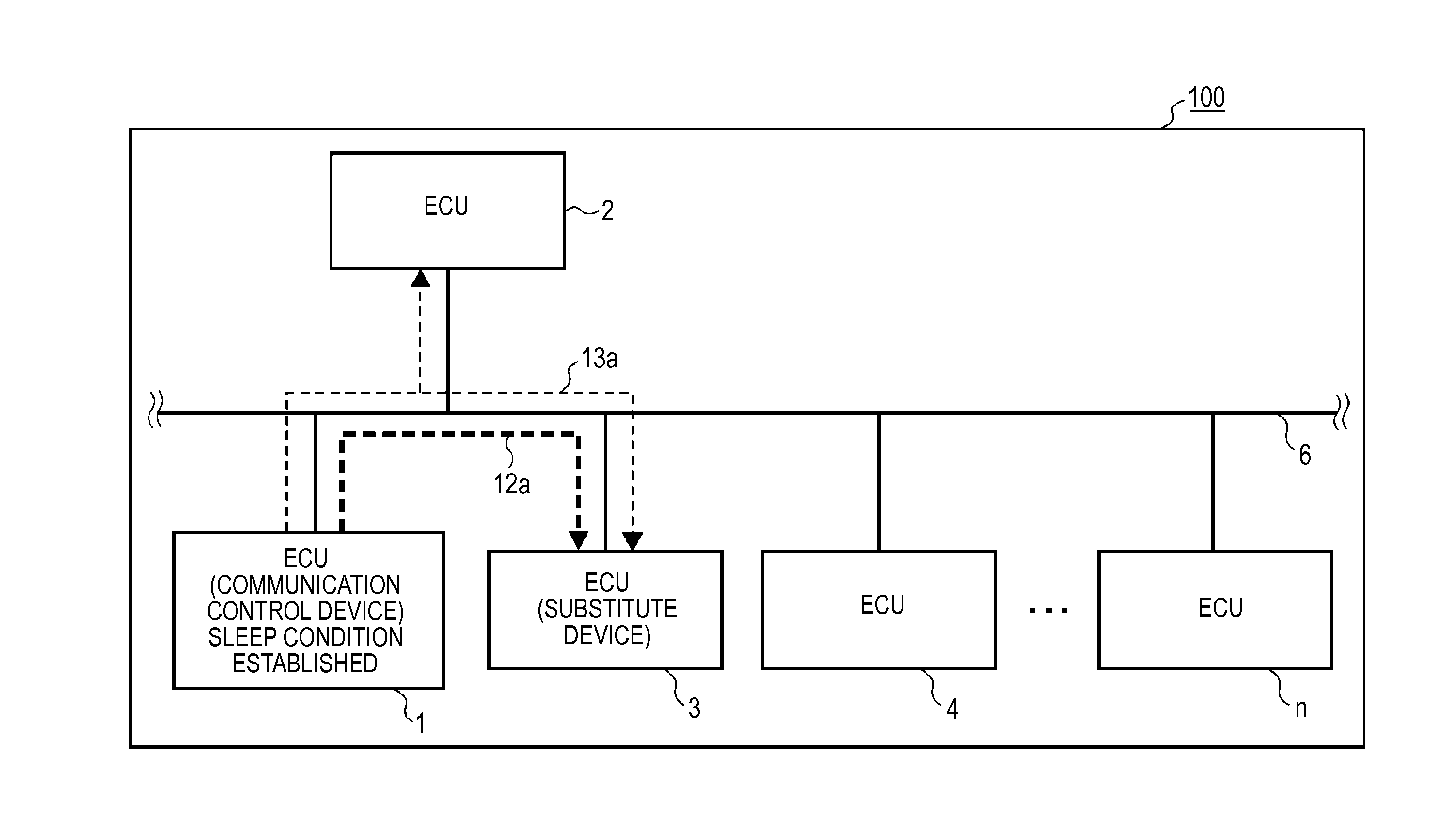
[0053]Hereinbelow, a control device switching system according to a first preferred embodiment of the invention will be described with reference to the drawings. FIG. 1 is a diagram showing the configuration of a control device switching system according to the first preferred embodiment. It should be noted that the same or corresponding component parts are designated by the same reference numerals in all the drawings referred to hereinbelow, to avoid repetitive description.

[0054]A control device switching system 100 according to the first preferred embodiment is one in which a plurality of control devices ECUs 1 to n (n>3) incorporated in a vehicle are connected to each other via a network 6, which is a common communication line. These control devices include a communication control device that performs transmission and reception of data with other control devices than itself, and a plurality of substitute candidate devices that are capable of taking over a data transmission proces...

second preferred embodiment

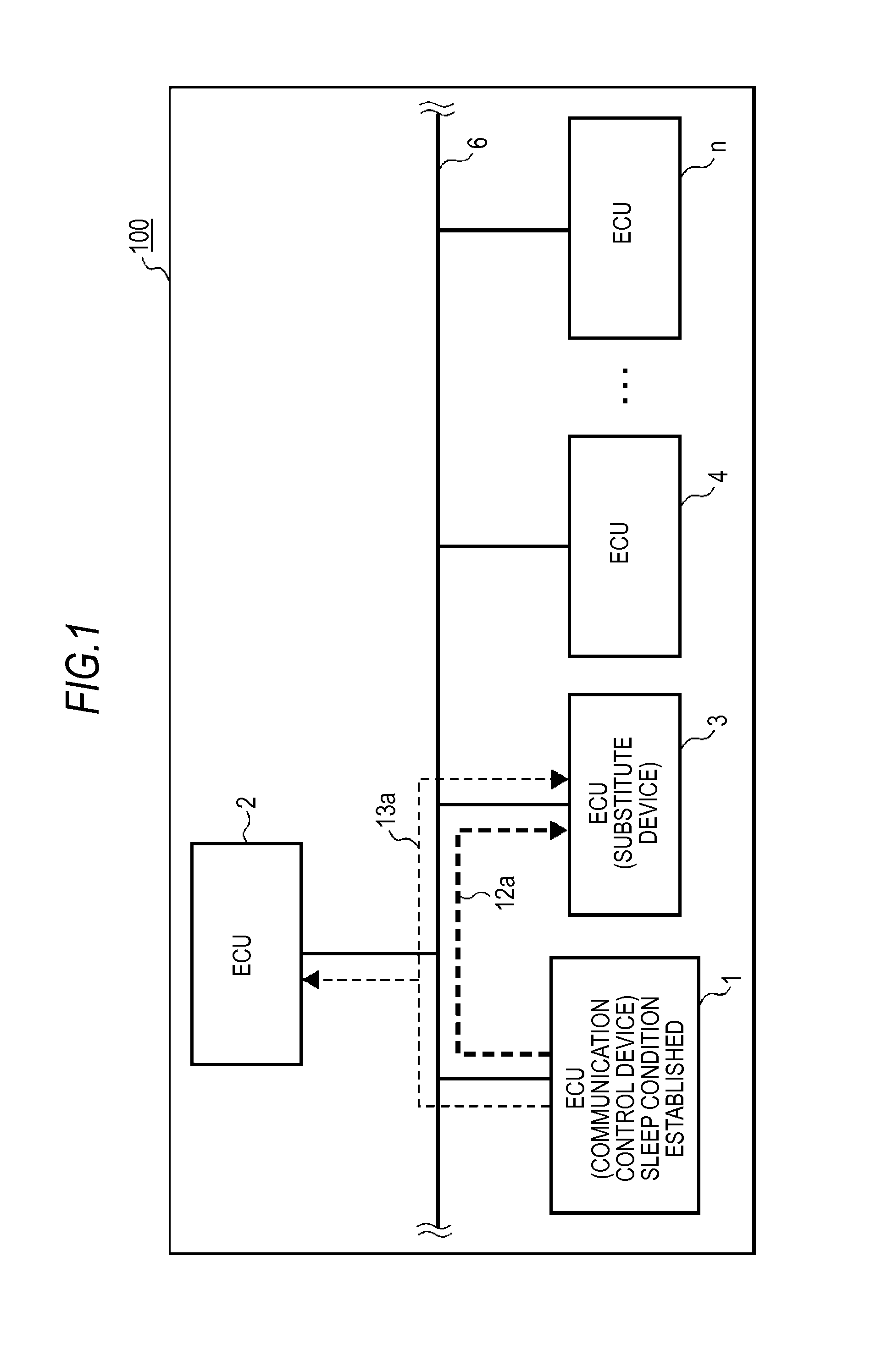
[0092]FIG. 10 shows the configuration of a control device switching system 100A according to a second preferred embodiment of the invention. FIG. 11 shows the configuration of a substitute candidate device ECU 2 in the second preferred embodiment. The configuration of the communication control device ECU 1 in the second preferred embodiment is the same as in the above-described first preferred embodiment, so the description thereof again refers to FIG. 2A.

[0093]In the control device switching system 100A, each of the substitute candidate devices ECUs 2 to m includes a substitution request transmitting unit 22, which is the second substitution request transmitting unit, and a substitute transmission acceptability determining unit 23, which is the second substitute transmission acceptability determining unit. The substitution request transmitting unit 22 transmits a substitution request to a substitute candidate device other than its own that is assigned to takeover the data transmiss...

third preferred embodiment

[0111]FIG. 16 shows the configuration of a control device switching system 100C according to a third preferred embodiment of the invention. FIG. 17A shows the configuration of a communication control device ECU 1, and FIG. 17B shows the configuration of a substitute candidate device ECU 2. The drawings and descriptions thereof are omitted, because the configuration of the other substitute candidate devices ECUs 3 to m is the same as that of the ECU

[0112]The communication control device ECU 1 in the third preferred embodiment has the data transmission-reception executing / stopping unit 11, the substitution request transmitting unit 12, the sleep condition establishment determining unit 14, the sleep process unit 15, and the wake-up process unit 16. In addition, the ECU 1 has a temporary storage device 7 (see FIG. 18) configured to temporarily store the results of determination by a substitution request transmitting unit 22A, which are transmitted from the ECUs 2 to m. On the other han...


PUM


Abstract

Before a communication control device ECU falls into a sleep state or a power-off state, a substitution request is transmitted to an ECU, among substitute candidate devices ECU to ECU, that is determined by a substitute transmission acceptability determining unit as being capable of taking over the communication control device. A substitution-capable processing load quantity, a substitution-capable process importance level, or a failure determination result of each of the ECUs is used as determination criteria when the substitute transmission acceptability determining unit of the ECU determines a substitute device, and the determination is carried out in an order that takes into consideration the process importance level of each of the ECUs during travelling or at a standstill, to prevent failures in a network or abnormal behaviors of a vehicle.

Description

BACKGROUND OF THE INVENTION[0001]1. Field of the Invention[0002]The present invention relates to a control device switching system for switching a control device that performs communication between a plurality of control devices that are incorporated in a vehicle and connected to each other via a common communication line.[0003]2. Description of the Background Art[0004]A plurality of control devices called ECUs (Electronic Control Units) are incorporated in a vehicle. Those control devices perform transmission and reception of information via a common communication line to achieve the operations of the vehicle in cooperation with one another. These control devices are supplied with electric power from a battery, an alternator / motor, and the like that are incorporated in the vehicle. However, as the number of the control devices incorporated in a vehicle increases in recent years, the amount of electric power consumed by the control devices tends to increase accordingly. When the amo...

Claims


Application Information

Patent Timeline
IPC IPC(8): B60R16/023B60W50/04H04L69/40
CPCB60R16/023B60W2600/00B60W50/045B60W2050/0006
Inventor OKUYAMA, HIROSHIMORITA, TORUMATSUI, TOSHINORIBABA, MADOKAMORITA, KIYOHIRO
Owner MITSUBISHI ELECTRIC CORP
Why Eureka
Try Eureka