
Rotating induction grow light system

a technology of induction grow light and grow light, which is applied in the direction of lighting support devices, lighting applications, light source combinations, etc., can solve the problems of high heat discharge, low power efficiency, and major problems of attenuation of light, so as to achieve less electricity, produce so little heat, and not burdened by extra labor and costs.

Inactive Publication Date: 2016-01-07
GLOBAL LIGHTING TECH LLC
View PDF19 Cites 9 Cited by
  • Summary
  • Abstract
  • Description
  • Claims
  • Application Information

AI Technical Summary

Benefits of technology

The rotating induction grow light system has several advantages over previous lighting systems. It provides a single system that can support both vegetative and flowering growth, reducing the need for different lamps and storage. The bulbs last longer and use less electricity and produce less heat, making it more energy-efficient. The system can also be guaranteed for 5 years and can be used for 10 with proper maintenance. Overall, this system is a cost-effective and efficient way to support both stages of plant growth.

Problems solved by technology

The HID lamps have been a mainstay in the indoor gardening market for over 20 years, but they have many problems, such low power efficiencies, high heat discharge, etc.
Attenuation of light is a major issue faced by plant growers around the world.
With HID lamps, this is hard to do because of the heat that these lamps produce.
Heat produced by a light fixture is always a design challenge and concern.
The HID lamps by consequence of high lumen output with low power efficiencies produce undesirable amounts of heat.
This then wastes energy and removes from the greenhouse carbon dioxide that has been added therein and that the plants need for photosynthesis.
This poses problems though when lamps or light bulbs need to be changed.
This is costly, not only in terms of storage and space, but also in the labor that is required to switch out bulbs and / or lamps at the different stages of plant growth.

Method used


Image

  • Rotating induction grow light system
  • Rotating induction grow light system
  • Rotating induction grow light system

Examples


Embodiment Construction

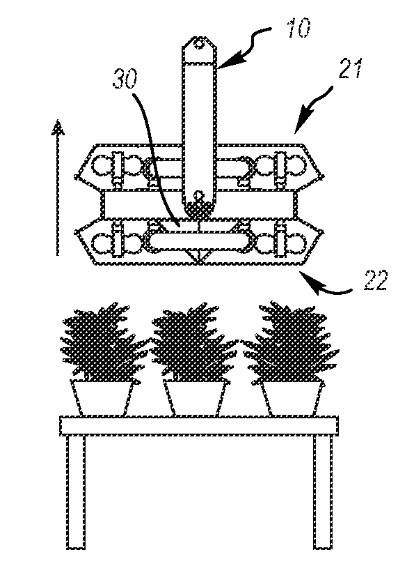
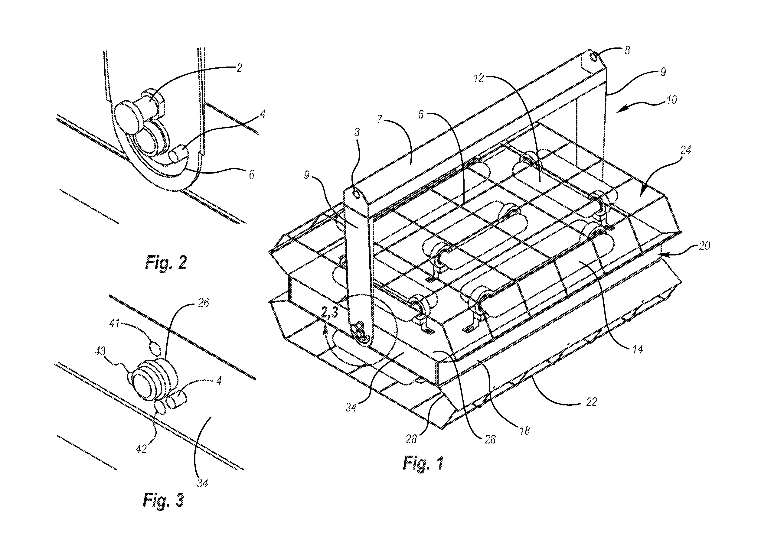
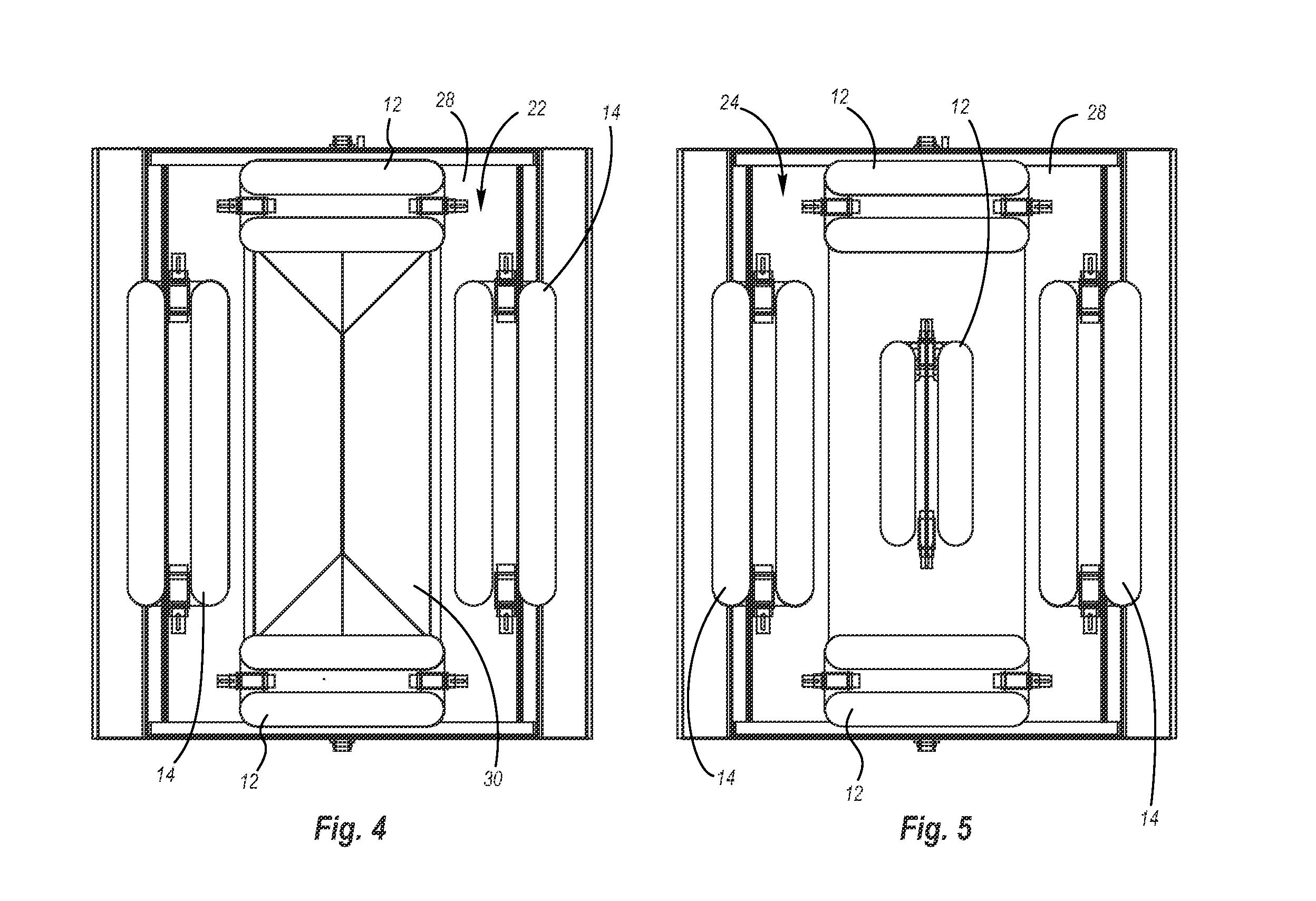
[0055]This document features a rotating induction grow light system. There are many features of rotating induction grow light system and method implementations disclosed herein, of which one, a plurality, or all features or steps may be used in any particular implementation.

[0056]In the following description, reference is made to the accompanying drawings which form a part hereof, and which show by way of illustration possible implementations. It is to be understood that other implementations may be utilized, and structural, as well as procedural, changes may be made without departing from the scope of this document. As a matter of convenience, various components will be described using exemplary materials, sizes, shapes, dimensions, and the like. However, this document is not limited to the stated examples and other configurations are possible and within the teachings of the present disclosure. As will become apparent, changes may be made in the function and / or arrangement of any o...


PUM


Abstract

A rotating induction growth light system and method are disclosed. The rotating induction growth light includes a mounting bracket assembly and a light source assembly rotatably coupled to the mounting bracket assembly. The light source assembly has a first side subassembly and a second side sub assembly opposite the first side subassembly. The light source assembly is configured to rotate between a first position wherein the first side subassembly is facing away from the mounting bracket assembly and at least a second position wherein the second subassembly is facing away from the mounting bracket assembly. A method of providing light to a plant is disclosed, including: directing a vegetative side subassembly of a light source assembly toward a plant; and rotating the light source assembly until a flowering side subassembly is directed toward the plant, the flowering side subassembly positioned on the light source assembly opposite the vegetative side subassembly.

Description

CROSS-REFERENCE TO RELATED APPLICATION[0001]This application claims the benefit of the filing date of U.S. Provisional Patent Application 62 / 020,317 entitled “ROTATING INDUCTION GROWTH LIGHT SYSTEM”, filed on Jul. 2, 2014, which is hereby incorporated by reference in its entirety.BACKGROUND[0002]1. Technical Field[0003]Aspects of this document relate generally to rotating induction grow light system and method.[0004]2. Background Art[0005]Indoor gardens, green houses, hydroponics systems, and isolated carbon dioxide growing chambers all require light to grow plants. Currently, the most common grow-light source is HID (High Intensity Discharge) lamps constructed from high-pressure sodium and metal halide technologies. The HID lamps have been a mainstay in the indoor gardening market for over 20 years, but they have many problems, such low power efficiencies, high heat discharge, etc.[0006]Attenuation of light is a major issue faced by plant growers around the world. Plant growers wou...

Claims


Application Information

Patent Timeline
Patent Type & Authority Applications(United States)
IPC IPC(8): A01G7/04F21S8/04F21V7/04F21V21/30F21V33/00
CPCA01G7/045F21V7/04F21W2131/40F21V21/30F21S8/043F21V33/0004A01G9/249F21V23/02F21Y2113/00A01G9/20F21V7/041F21V15/015F21V23/04Y02P60/14
Inventor KOERNER, KURTELLISON, GREGORY L.
Owner GLOBAL LIGHTING TECH LLC
Learn More