Backlight module driving system and driving method thereof

a driving system and backlight module technology, applied in the direction of electric digital data processing, instruments, computing, etc., can solve the problems of increasing the power increasing the cost of unnecessary power consumption, and increasing the energy consumption of the lcd panel, so as to reduce the actual power consumption, and increase the luminance

Inactive Publication Date: 2012-05-24
CHUNGHWA PICTURE TUBES LTD
View PDF4 Cites 10 Cited by
  • Summary
  • Abstract
  • Description
  • Claims
  • Application Information

AI Technical Summary

Benefits of technology

[0009]The objective of the present invention is to provide a backlight system and a light source providing method, so as to decrease power consumption of a display by adjusting luminance of a backlight module during operation of presenting a 3D image.
[0013]Characteristics of the present invention are as follows. In the present invention, when a 3D image signal is displayed, a backlight module is controlled by a backlight driver to switch luminance. During data writing, the backlight module is disabled, or the luminance is decreased; and during a VBI, the backlight module is enabled, or the luminance is increased; so as to reduce actual power consumption and improve image quality when an LCD presents a 3D image screen, thus requiring less electricity and lower power consumption than that in the prior art. Therefore, the consumed power of an LCD panel is effectively decreased, life of components is elongated, actual energy consumption is decreased, and unnecessary power consumption cost is avoid.

Problems solved by technology

Therefore, the backlight module is in a useless power consumption state during most of the time, thus resulting in gratuitous waste of energy, increasing power consumption of an LCD panel, making a result of comparison between operating efficiency of the LCD panel, a life of a component, and actually consumed energy uneconomical, and increasing unnecessary power consumption cost.
Therefore, how to decrease power consumption of a display when the display presents a 3D image becomes a problem manufactures should contemplate.

Method used


Image

  • Backlight module driving system and driving method thereof
  • Backlight module driving system and driving method thereof
  • Backlight module driving system and driving method thereof

Examples


Embodiment Construction

[0024]Preferred embodiments of the present invention are described below in detail with reference to the accompanying drawings.

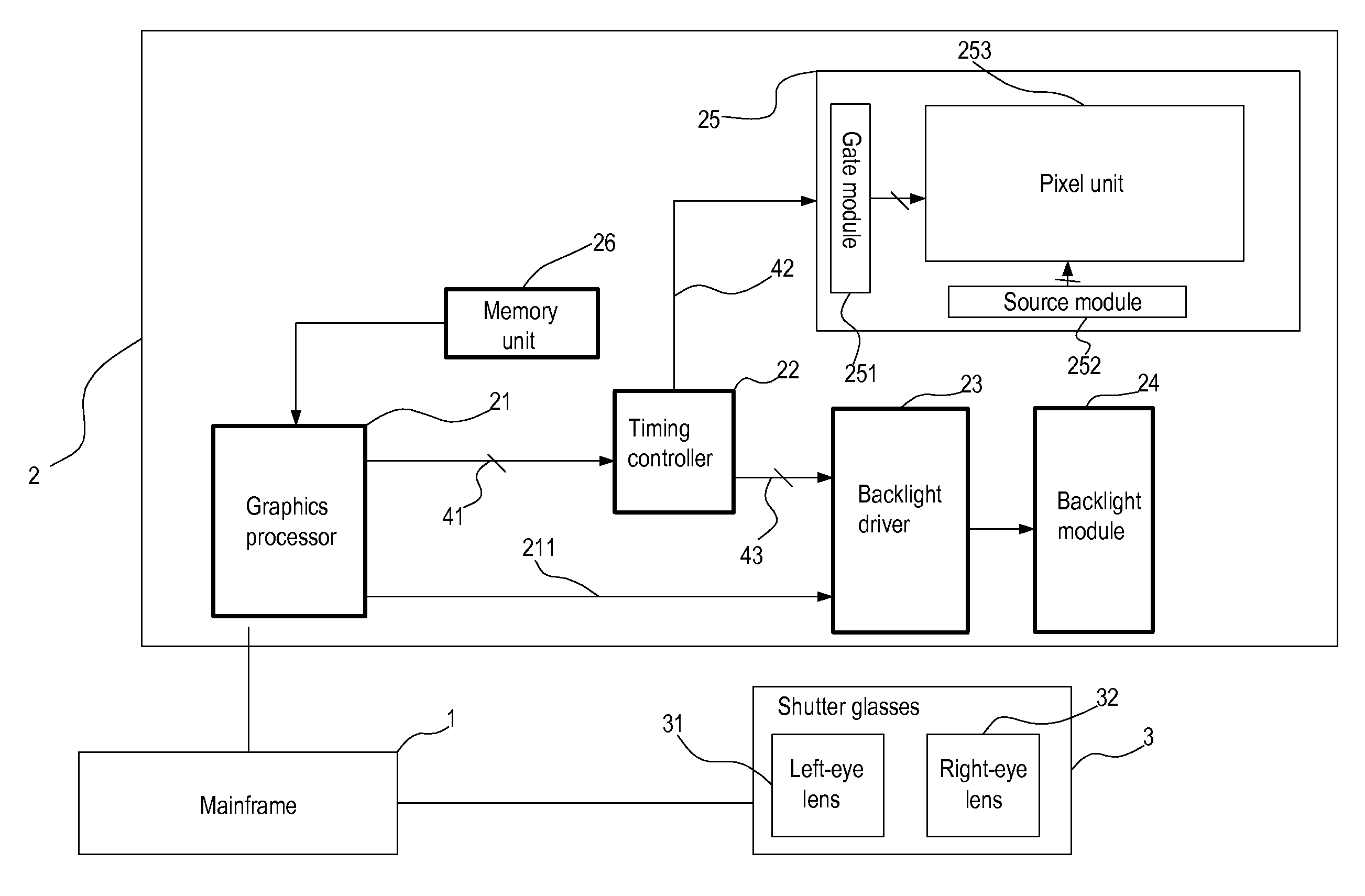
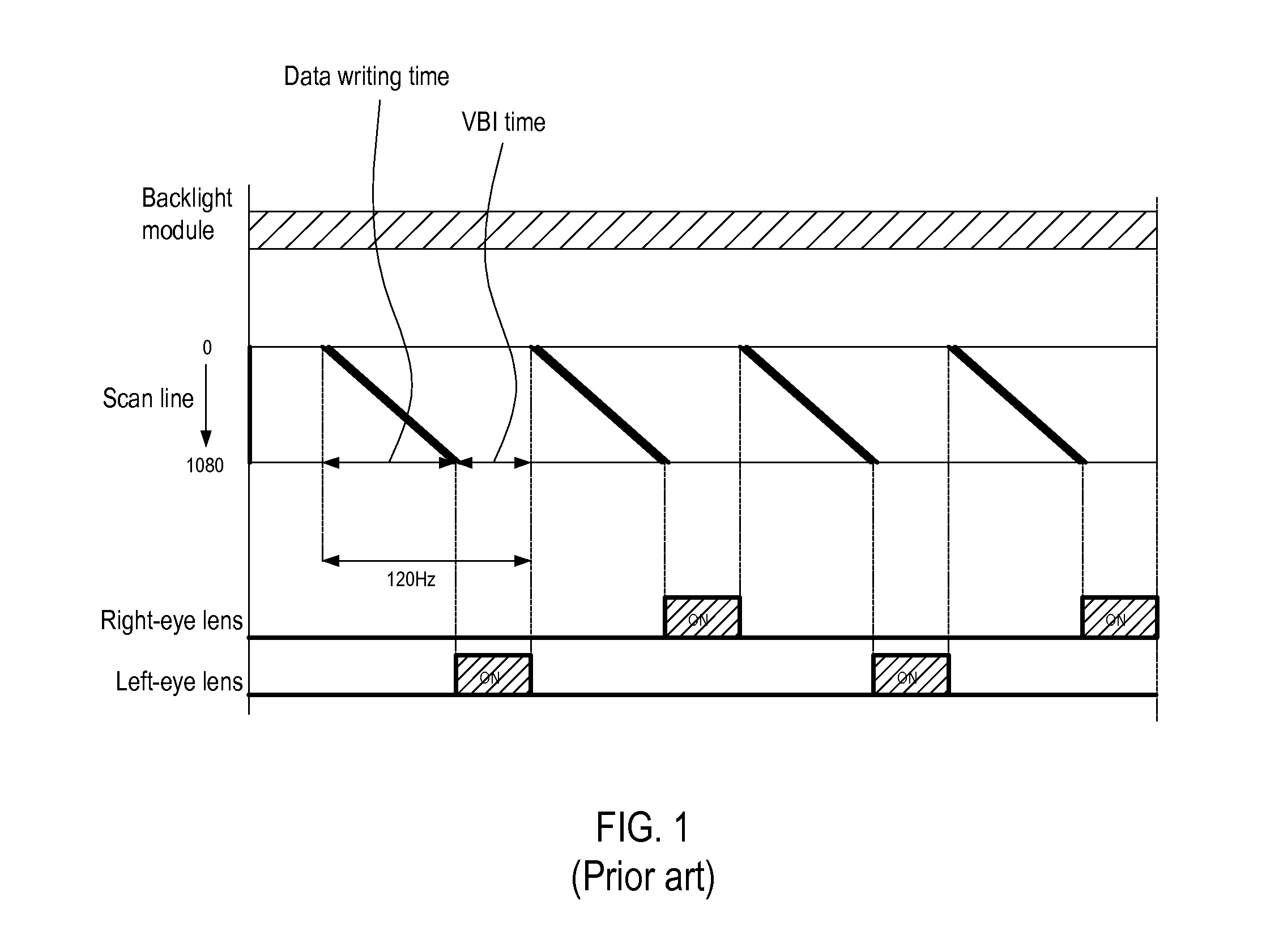
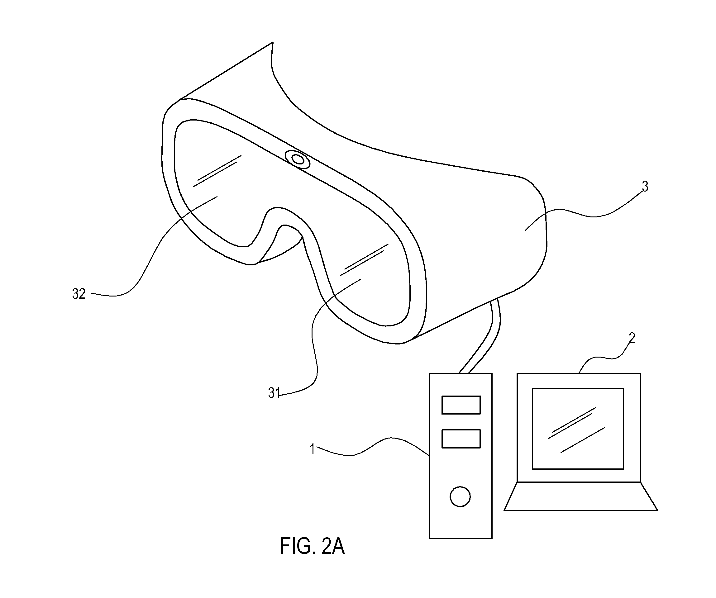
[0025]Referring to FIG. 2A, a schematic view of a first equipment architecture of a backlight module driving system according to an embodiment of the present invention is shown. Referring to FIG. 2B, a schematic view of the first equipment architecture of the backlight module driving system according to the embodiment of the present invention is shown. Referring to FIG. 3, a schematic operating timing diagram of a backlight system according to the embodiment of the present invention is shown. As shown in FIG. 2A, a mainframe 1 is connected to an LCD 2. The mainframe 1 is connected to shutter glasses 3 in a wired or wireless manner. The shutter glasses 3 include a left-eye lens 31 and a right-eye lens 32. The mainframe 1 is used to control the LCD 2 and the shutter glasses 3 to perform an image synchronous operation for displaying images. A technology of oper...


PUM


Abstract

A backlight module driving system and a driving method thereof are applied to a Liquid Crystal Display (LCD). In the LCD, a timing controller obtains a three-dimensional (3D) image signal provided by a graphics processor, generates a Liquid Crystal (LC) driving control signal, and generates a corresponding light adjusting signal according to a data writing time and a Vertical Blanking Interval (VBI) time of the LC driving control signal. A backlight driver obtains and analyzes the light adjusting signal, so as to disable a backlight module during the data writing time, and enable the backlight module during the VBI time.

Description

CROSS-REFERENCE TO RELATED APPLICATION[0001]This application claims the benefit of Taiwan Patent Application No. 099139929, filed on Nov. 19, 2010, which is hereby incorporated by reference for all purposes as if fully set forth herein.BACKGROUND OF THE INVENTION[0002]1. Field of Invention[0003]The present invention relates to a backlight system of a Liquid Crystal Display (LCD), and more particularly to a backlight module driving system and a driving method thereof.[0004]2. Related Art[0005]FIG. 1 is a schematic system driving timing diagram of three-dimensional (3D) image shutter glasses of the prior art. In the prior art, a 3D image display technology includes a glasses-based technology. In a shutter-based 3D image technology, a 3D image effect is achieved mainly by increasing a high update frequency (higher than 120 Hz / screen) of a screen, which is an active 3D image technology. After a 3D image signal is provided for a display, a screen with an update frequency being 120 Hz pre...

Claims


Application Information

Patent Timeline
Patent Type & Authority Applications(United States)
IPC IPC(8): G09G3/36G09G5/00
CPCG09G3/003G09G3/3406G09G2320/064G09G2310/08G09G2320/0252G09G3/3648
Inventor LIN, SHIN-CHANGCHEN, BI-HSIENCHIU, CHUN-CHIEHCHEN, CHIEN-YANGHUANG, TIEN-YUNG
Owner CHUNGHWA PICTURE TUBES LTD
Why Eureka
Try Eureka