
Location of a distress beacon

a beacon and distress technology, applied in the field of satellite communications, can solve the problems of poor signal processing sequence, 10 db degradation, and link budget reduction with respect to the current leosar version, and achieve the effect of improving signal processing sequence, avoiding significant cost impact, and optimizing the calibration of the antenna array

Inactive Publication Date: 2016-01-07
CENT NAT DETUD SPATIALES C N E S +1
View PDF7 Cites 14 Cited by
  • Summary
  • Abstract
  • Description
  • Claims
  • Application Information

AI Technical Summary

Benefits of technology

The patent describes a method for improving the performance of search and rescue signals. The method first checks for a line and then searches for a synchronization word to eliminate interference. This reduces complexity and allows for better operational performance. The method also allows for the enrichment of the position estimate and detection of jammers. Additionally, it enables recalculations and ease of looking back into the past.

Problems solved by technology

In most instances, the vast majority of beacons on the market do not allow association with an identifier that is unique with each beacon.
One of the main technical problems with the switch to MEOSAR is the degradation in the link budget with respect to the current LEOSAR version.
In fact, there is a risk that an antenna that is poorly oriented and / or lacking in transmission power, or alternatively a beacon that is partially submerged might not be located in the future.
Despite all these factors, the loss associated with the switch to MEOSAR leads to a 10 dB degradation.
In addition, one key problem is the cost of the antenna which means that the number of satellites tracked is limited vary greatly, typically to 4 or 5 (with a maximum of 8 for the most well endowed MEOLUT stations, although some on the other hand have just two antennas), whereas 30 satellites are typically visible across all of the constellations tracked.

Method used


Image

  • Location of a distress beacon
  • Location of a distress beacon
  • Location of a distress beacon

Examples


Embodiment Construction

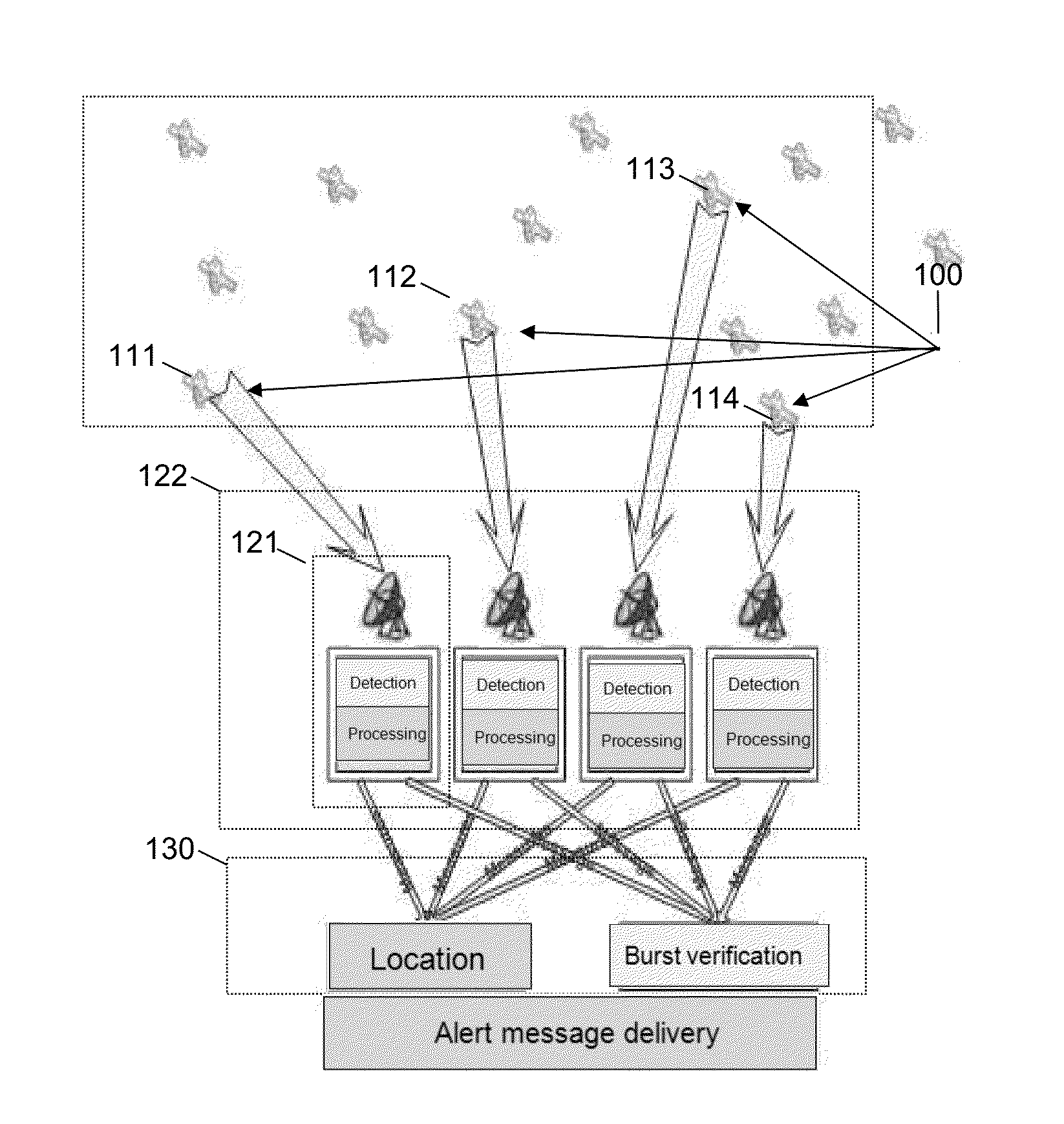
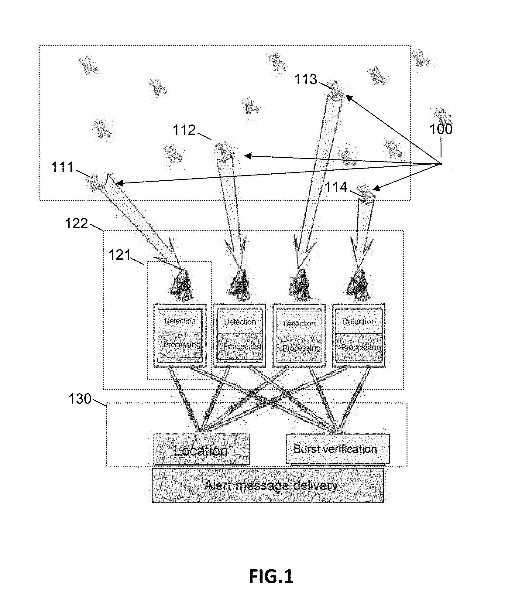
[0069]FIG. 1 illustrates the overall operation of the existing methods for locating a distress beacon. A beacon 100 transmits an electromagnetic signal, which is received by four satellites 111, 112, 113 and 114, from among a constellation of satellites. These four satellites forward the distress signal to the ground stations. The MEOLUT ground station 122 is made up of stations 121 of LEOLUT type. At the present time, around ten MEOLUT stations 122 are deployed worldwide. A LEOLUT 121 is associated with one antenna and sees just one satellite. Each LEOLUT station performs four successive FOA / TOA (time of arrival, frequency of arrival) measurements, with a Doppler measurement (the Doppler effect being strong at low altitudes). With four LEOLUT stations forming one MEOLUT, the beacon is located (the position of the satellites is known at each instant), with one single “burst”.

[0070]According to the prior art, these various stations 121 do not work together. The processing channels ar...


PUM


Abstract

There is disclosed a computer implemented method for processing the signal emitted by a distress beacon, the signal being received by several satellites and forwarded to at least one ground station, the method comprising the steps consisting in determining a set of hypothetical positions of the beacon, and for at least one of the hypothetical positions, for each satellite, offsetting the signal received and forwarded as a function of the hypothetical position; summing the offset signals; and evaluating the validity of the sum of the offset signals as a function of the presence of a predefined characteristic in the sum. Developments describe aspects such as the temporal and / or frequency offsetting, the construction of a digital replica of the signal transmitted by the beacon, and as the minimizing of the weighted residues of the offsets. System aspects are described, including the calibration of an active antenna or an array of antennas.

Description

CROSS-REFERENCE TO RELATED APPLICATION[0001]This application claims priority to foreign French patent application No. FR 1401510, filed on Jul. 4, 2014, the disclosure of which is incorporated by reference in its entirety.FIELD OF THE INVENTION[0002]The invention relates to the field of satellite communications and in particular that of the procedures and methods for locating a distress beacon.BACKGROUND[0003]A distress beacon or “radio beacon” for locating incidents is a transmitter which transmits an emergency electromagnetic signal (better known as a “burst”) to give the position of a ship, an airplane or an individual in distress. This signal is received by one or more satellites of a network (for example Cospas-Sarsat or GEOSAR) which generally forward this signal to ground stations which determine the location of the beacon and transmit the coordinates thereof to the nearest search and rescue center.[0004]The signal may contain information about the position taken by GPS, maki...

Claims


Application Information

Patent Timeline
Patent Type & Authority Applications(United States)
IPC IPC(8): G01S19/17G01S5/00G01S19/42
CPCG01S5/0072G01S19/42G01S19/17G01S5/0081G01S5/0231G01S5/06H04B7/18513G01S5/02213
Inventor CALMETTES, THIBAUD PIERRE JEANPETCU, EMANUELA ANA MARIAGREGOIRE, YOAN
Owner CENT NAT DETUD SPATIALES C N E S
Learn More