Linear vibration motor

Active Publication Date: 2016-01-14
AAC TECH PTE LTD
View PDF19 Cites 44 Cited by
  • Summary
  • Abstract
  • Description
  • Claims
  • Application Information

AI Technical Summary

Problems solved by technology

In such case, the vibration damping is too low and thus the value of the quality factor of the v

Method used


Image

  • Linear vibration motor
  • Linear vibration motor
  • Linear vibration motor

Examples


Embodiment Construction

[0012]Reference will now be made to describe the exemplary embodiment of the present invention in detail.

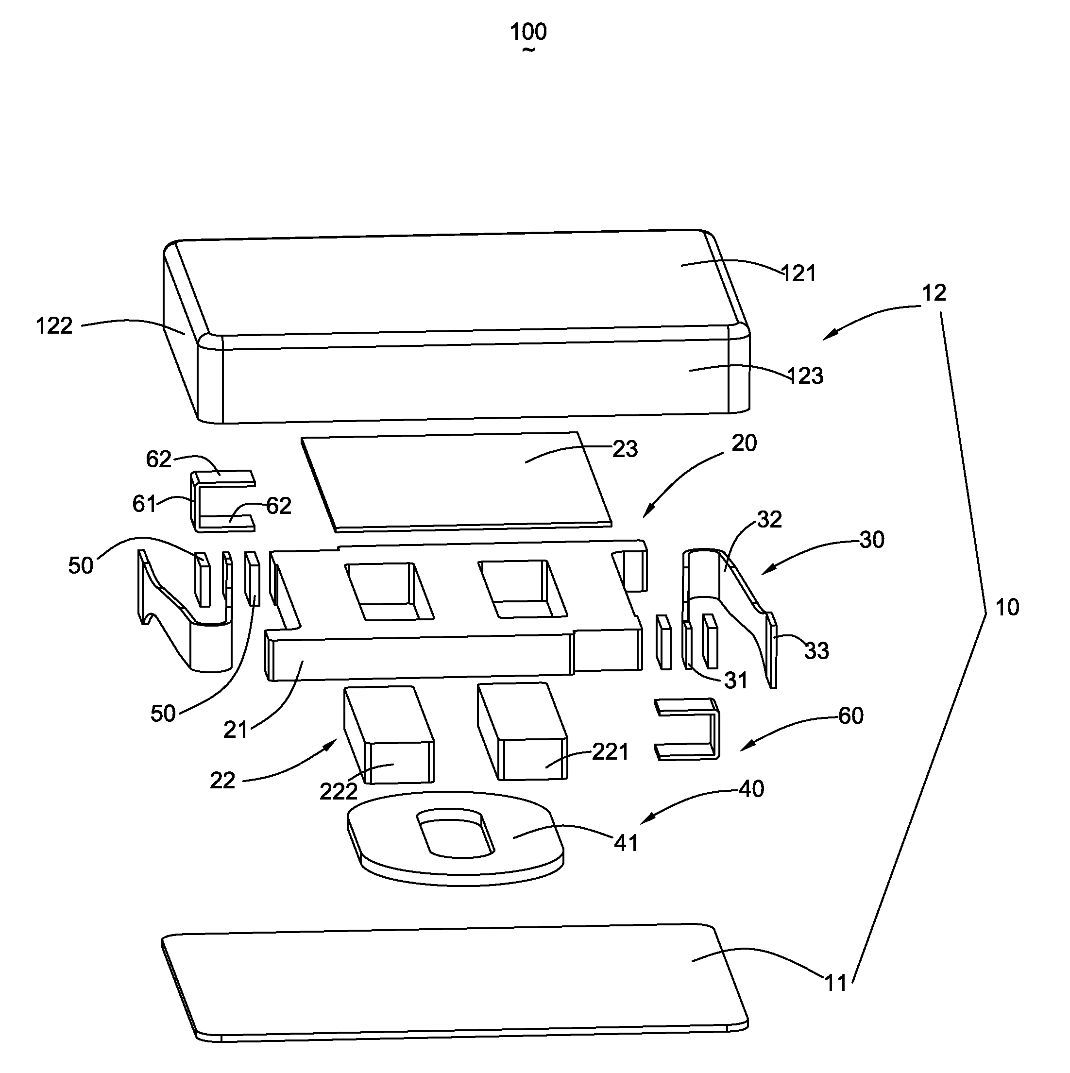
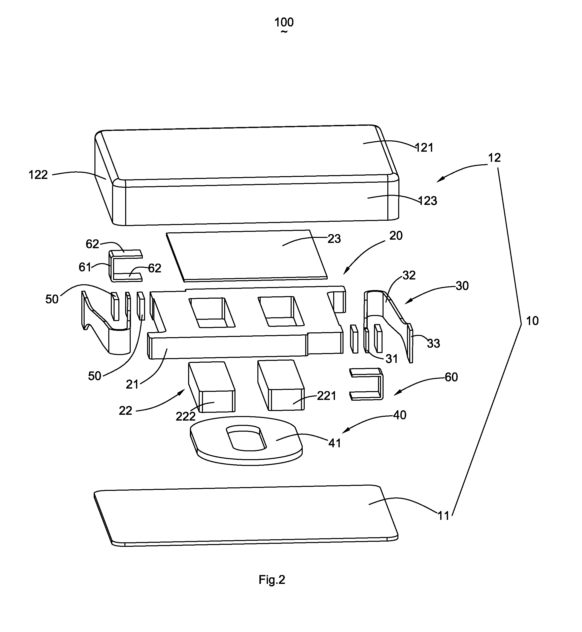
[0013]With reference to FIG. 1 through FIG. 5, a linear vibration motor 100 according to an exemplary embodiment of the present disclosure comprises a housing 10, a plurality of elastic members 30 received in the housing 10, a vibrator unit 20 suspended in the housing by the elastic members 30, a stator unit 40 fixed on the housing 10 and keeping a distance from the vibrator unit 20, at least one pair of dampers 50 adjacent to ends of the elastic members 30 and been in contact with the ends of the elastic members 30, and clamping members 60 clamping the ends of the elastic members 30 and the dampers 50 to the vibrator unit 20 for fixing the elastic members 30 and the dampers 50 to the vibrator unit 20.

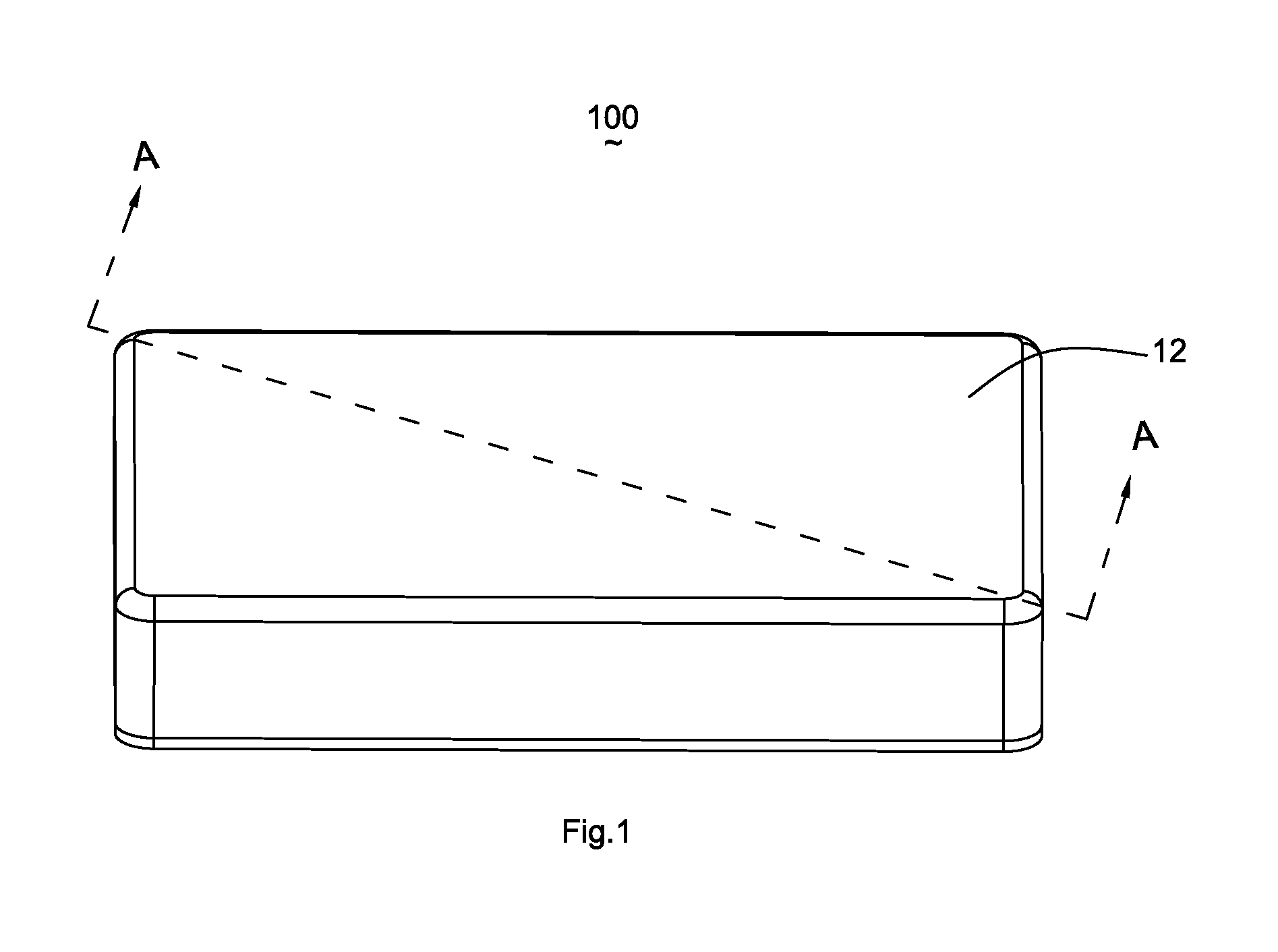
[0014]The housing 10 comprises a base 11 and a cover 12 assembled with the base 11 to form an inner space 13. The housing 10 may be, but not limited to, rectangular cuboid shape. Th...


PUM


Abstract

A linear vibration motor is disclosed in the present disclosure. The linear vibration motor includes a housing including a cover and a base associated with the cover to form an internal space; a pair of elastic members received in the internal space, each of the elastic member including a first connecting portion and an elastic arm extending from the first connecting portion and connected with the cover; an vibrator unit suspended in the internal space by the elastic members; a stator unit mounted on the base; a pair of dampers, each damper located on one side of the first connecting portion, and been in contact with the first connecting portion for absorbing vibrations of the vibrator unit; and a pair of clamping members, each clamping member clamping the first connecting portion and the damper to the vibrator unit.

Description

FIELD OF THE INVENTION[0001]The present invention relates to vibration motors, and more specifically to a vibration motor designed to be mounted on a portable devices to generate tactile vibration.DESCRIPTION OF RELATED ART[0002]In general, one of the key functions requisite for communication devices is a call reception function. Commonly used call reception functions include a sound generating function that generates a melody or a bell sound and a vibration function that transfers vibrations to a device.[0003]Among the functions, the vibration function is commonly used so as not to interfere with others by preventing a melody or a bell sound from being transferred to the exterior through a speaker.[0004]In order to implement such a vibration function, in general, a small vibration motor is driven to transfer driving force to a case of a device to make the device vibrate. The vibration motor related to the present art generally comprises a housing with a receiving space, a plurality...

Claims


Application Information

Patent Timeline
IPC IPC(8): H02K33/00
CPCH02K33/00H02K33/16
Inventor DONG, LEPING
Owner AAC TECH PTE LTD
Why Eureka
Try Eureka