Linear vibration generator

a generator and linear technology, applied in the field of linear vibration generators, can solve the problems of short operating life of motors using such brushes and commutators, wear and black powder, and slow response to touch made on the touch screen, so as to achieve stable linear vibration and prevent noise from occurring

Inactive Publication Date: 2011-04-21
MPLUS
View PDF18 Cites 42 Cited by
  • Summary
  • Abstract
  • Description
  • Claims
  • Application Information

AI Technical Summary

Benefits of technology

The present invention provides a linear vibration generator by which a stable linear vibration can be obtained and noise can be prevented from occurring.

Problems solved by technology

The vibration motor using such brush and commutator has a shorter operating lifetime due to mechanical friction and electrical sparks, which cause wear and black powder, while the brush moves between the segments of the commutator when the motor rotates.
Moreover, when voltage is supplied to the vibration motor, it takes time to reach the target amount of vibration, i.e., the magnitude by which it is sufficient for the user to sense the vibration, by the rotational inertia of the vibration motor, causing a slower response to the touch made on the touch screen.
In the linear vibration generator, however, the vibrating part may have friction with the stationary part due to shocks applied in a direction that is different from the linear direction of the vibrating part when the vibrating part vibrates.
If the amplitude of the vibrating part becomes wider, the vibrating part may collide with the stationary part, causing noise.

Method used


Image

  • Linear vibration generator
  • Linear vibration generator
  • Linear vibration generator

Examples


Embodiment Construction

As the invention allows for various changes and numerous embodiments, particular embodiments will be illustrated in the drawings and described in detail in the written description. However, this is not intended to limit the present invention to particular modes of practice, and it is to be appreciated that all changes, equivalents, and substitutes that do not depart from the spirit and technical scope of the present invention are encompassed in the present invention. In the description of the present invention, certain detailed descriptions of related art are omitted when it is deemed that they may unnecessarily obscure the essence of the invention.

The features and advantages of this invention will become apparent through the below drawings and description.

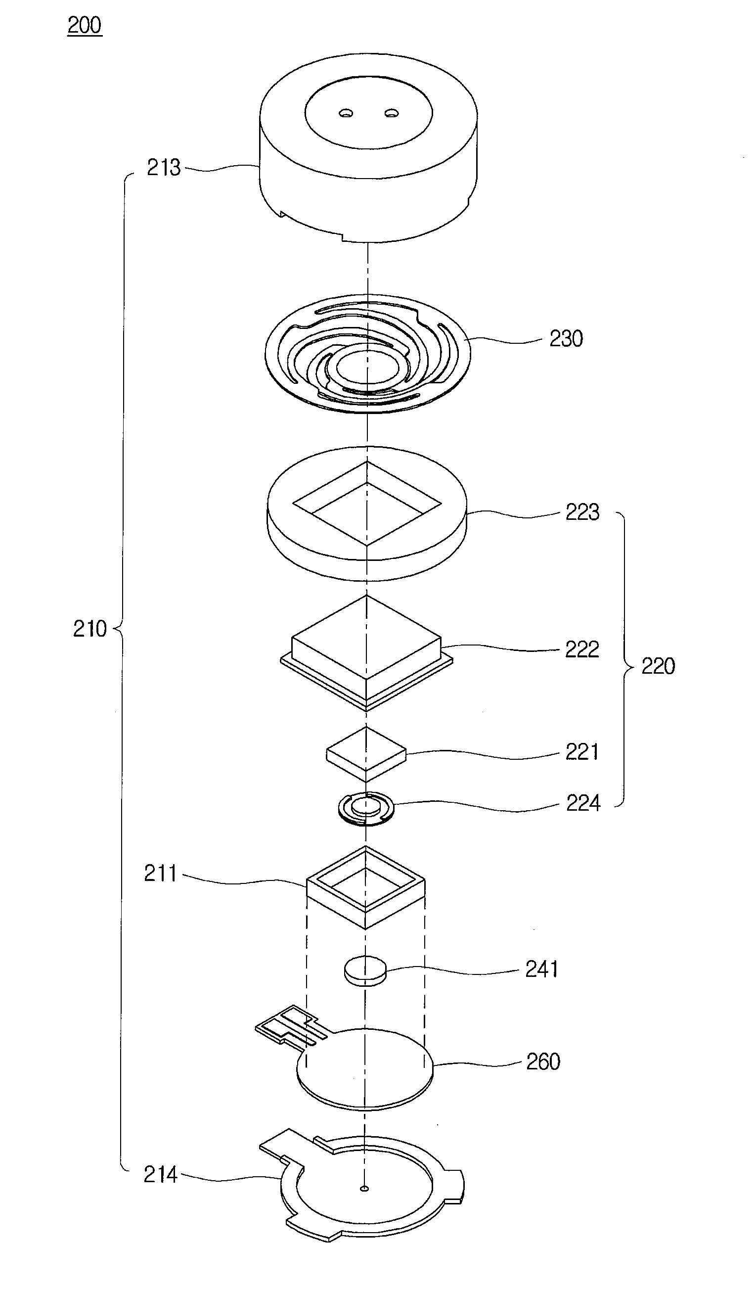
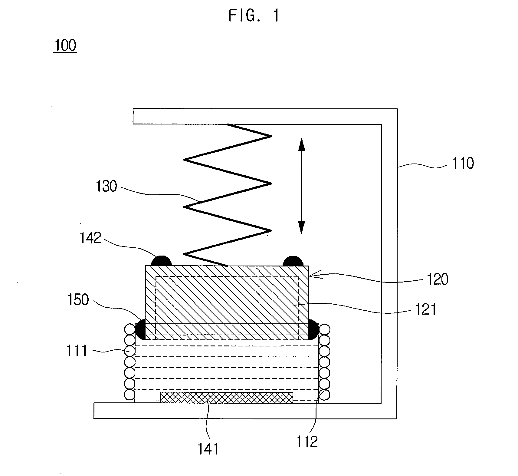
FIG. 1 illustrates the configuration of a linear vibration generator in accordance with an embodiment of the present invention.

Referring to FIG. 1, a linear vibration generator 100 in accordance with an embodiment of the present i...


PUM


Abstract

A linear vibration generator is disclosed. The linear vibration generator in accordance with an embodiment of the present invention includes a stationary part, which has a polygonal-prism-shaped coil and in which the polygonal-prism-shaped coil induces a magnetic field by having an electric current supplied, a vibrating part, which has a polygonal-prism-shaped magnet and in which a portion of the polygonal-prism-shaped magnet is inserted into the coil, an elastic member, which is coupled to the stationary part and elastically supports the vibrating part such that the vibrating part can move linearly, and a lubricating band, which is formed on an outer circumferential surface of the magnet.

Description

CROSS-REFERENCE TO RELATED APPLICATIONSThis application claims the benefit of Korean Patent Application No. 10-2009-0099555, filed with the Korean Intellectual Property Office on Oct. 20, 2009, the disclosure of which is incorporated herein by reference in its entirety.BACKGROUND1. Technical FieldThe present invention is related to a linear vibration generator.2. Description of the Related ArtA vibration motor is a part that converts electrical energy into mechanical vibrations by using the principle of generating electromagnetic forces, and is commonly installed in a mobile terminal, such as a mobile phone and a PDA, to generate a soundless vibrating alert. With the rapid expansion of mobile terminal markets and increased functionalities added to the mobile terminal, the mobile terminal is increasingly required to be smaller and better. As a result, there has been an increased demand for the development of a new structure of vibration motor that can overcome the shortcoming of conv...

Claims


Application Information

Patent Timeline
Patent Type & Authority Applications(United States)
IPC IPC(8): H02K35/02
CPCH02K33/16G06F3/016H02K33/06H02K35/02
Inventor CHOI, JUN-KUN
Owner MPLUS
Why Eureka
Try Eureka