
Linear vibration actuator

Inactive Publication Date: 2015-07-09
MPLUS
View PDF5 Cites 39 Cited by
  • Summary
  • Abstract
  • Description
  • Claims
  • Application Information

AI Technical Summary

Benefits of technology

The invention is a small vibration actuator that can be used in a portable electronic device. It helps create vibration without taking up too much space. Additionally, a damper member is included to protect components from damage.

Problems solved by technology

Thus, considering characteristics of the portable electronic device, miniaturization and thinness of the portable electronic device cannot but have a limitation due to the coin type linear vibrator.

Method used


Image

  • Linear vibration actuator
  • Linear vibration actuator
  • Linear vibration actuator

Examples


Embodiment Construction

[0030]Advantages and features of the present invention and methods of accomplishing the same will be apparent by referring to embodiments described below in detail in connection with the accompanying drawings. However, the present invention is not limited to the embodiments disclosed below and may be implemented in various different forms. The embodiments are provided only for completing the disclosure of the present invention and for fully representing the scope of the present invention to those skilled in the art.

[0031]For simplicity and clarity of illustration, the drawing figures illustrate the general manner of construction, and descriptions and details of well-known features and techniques may be omitted to avoid unnecessarily obscuring the discussion of the described embodiments of the invention. Additionally, elements in the drawing figures are not necessarily drawn to scale. For example, the dimensions of some of the elements in the figures may be exaggerated relative to ot...


PUM


Abstract

Embodiments of the invention provide a motor assembly including a terminal provided at a stator of a motor and electrically connected to a coil wound around the stator, and a controller formed with a coupling hole to which the terminal is coupled and electrically connected and controlling electric input and output to the terminal.

Description

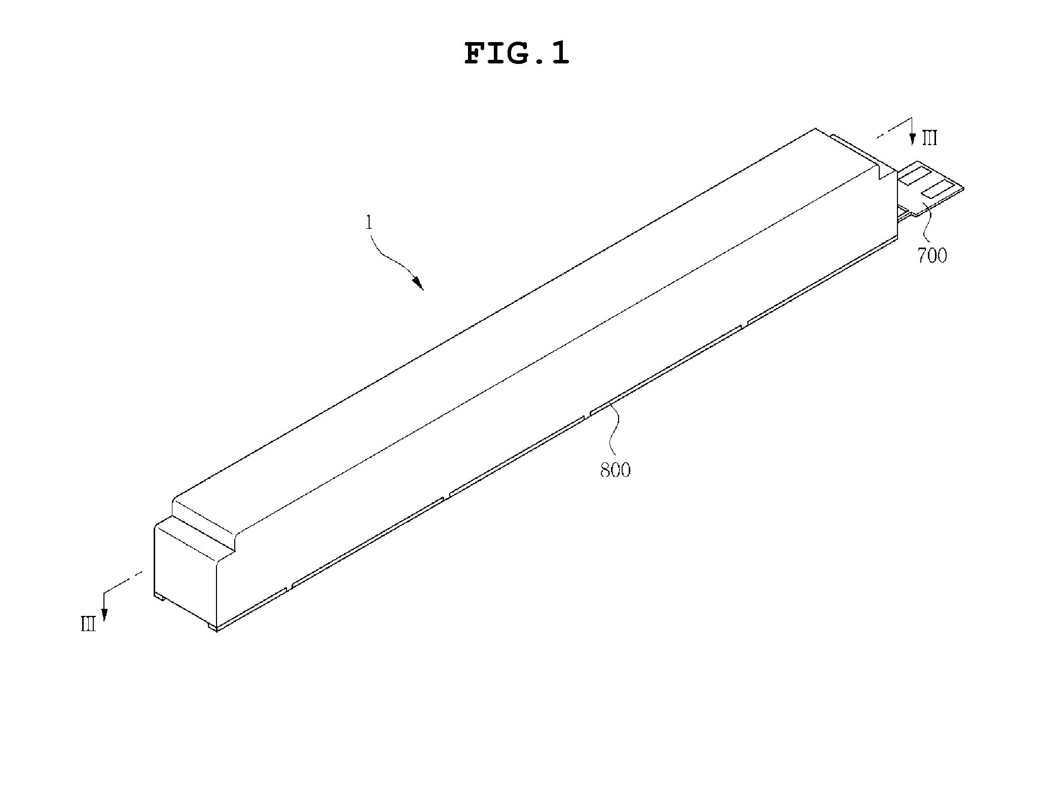
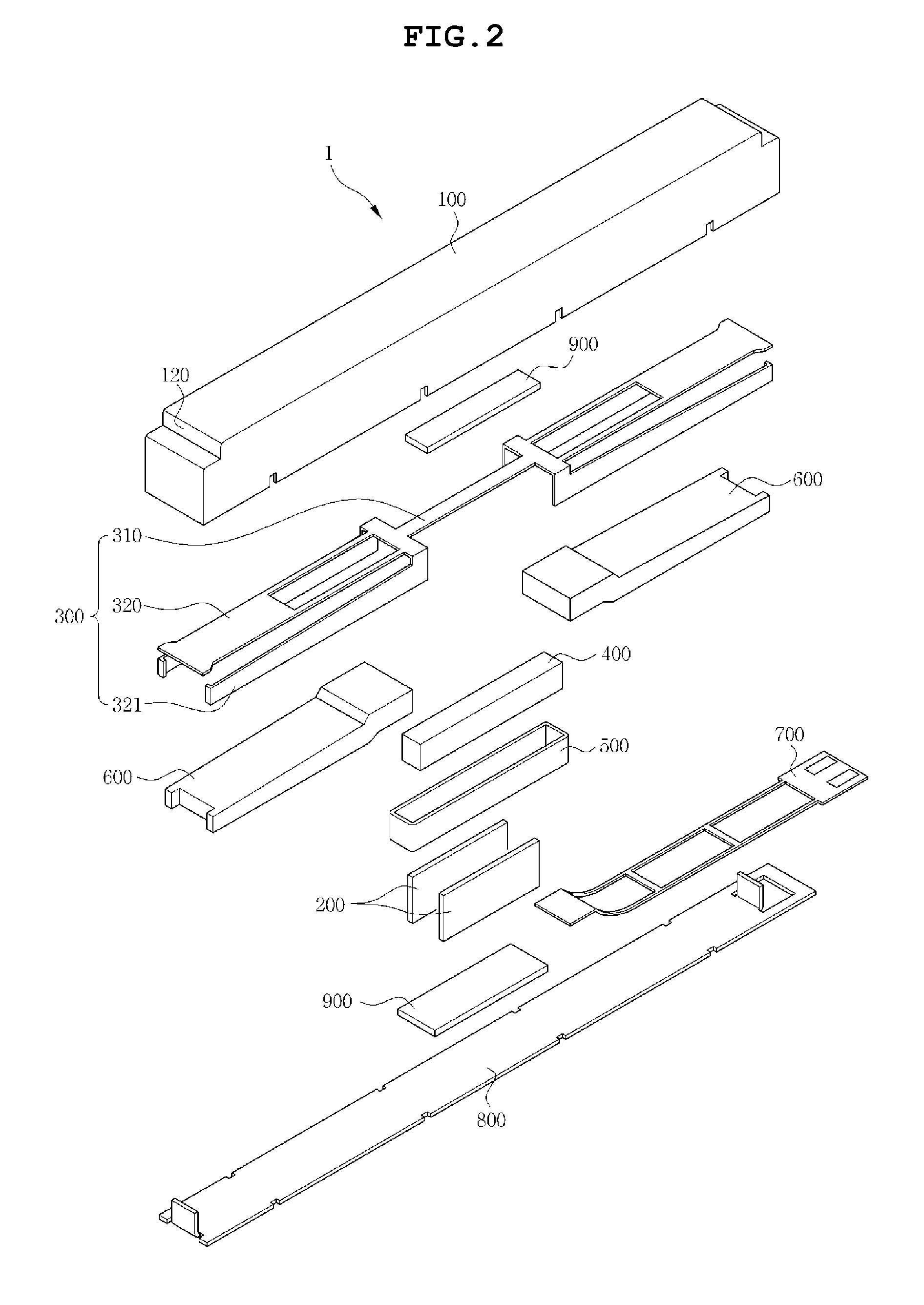
CROSS REFERENCE TO RELATED APPLICATION[0001]This application claims the benefit of and priority under 35 U.S.C. §119 to Korean Patent Application No. KR 10-2014-0002482, entitled “LINEAR VIBRATION ACTUATOR,” filed on Jan. 8, 2014, which is hereby incorporated by reference in its entirety into this application.BACKGROUND[0002]1. Field of the Invention[0003]The present invention relates to a linear vibration actuator, and more particularly, to a bar type linear vibration actuator.[0004]2. Description of the Related Art[0005]Generally, in portable electronic devices, such as a portable phone, an e-book terminal, a game machine, or a portable multimedia player (PMP), for example, a vibration function has been utilized for various applications.[0006]In particular, a vibration generating apparatus for generating the vibration has been mainly equipped in the portable electronic device to be used as an alert function that is a soundless receiving signal.[0007]To keep pace with multi-functio...

Claims


Application Information

Patent Timeline
IPC IPC(8): H02K33/18
CPCH02K33/18H02K33/00
Inventor KIM, YONG TAEYIM, JUNG KYULEE, KI YOUNG
Owner MPLUS
Learn More