Holding device

Inactive Publication Date: 2016-01-21
SYNCMOLD ENTERPRISE CORP
View PDF1 Cites 10 Cited by
  • Summary
  • Abstract
  • Description
  • Claims
  • Application Information

AI Technical Summary

Benefits of technology

[0023]In summary, the holding device of the present invention utilizes the rotating mechanism that the rotating arm is pivoted to the frame for holding the electronic device with two long sides or two short sides or for holding the two electronic devices with different sizes. The distance between the two ends of the rotating arm varies when the rotating arm rotates re

Problems solved by technology

Thus, it disadvantages the electro

Method used


Image

  • Holding device
  • Holding device
  • Holding device

Examples


Example

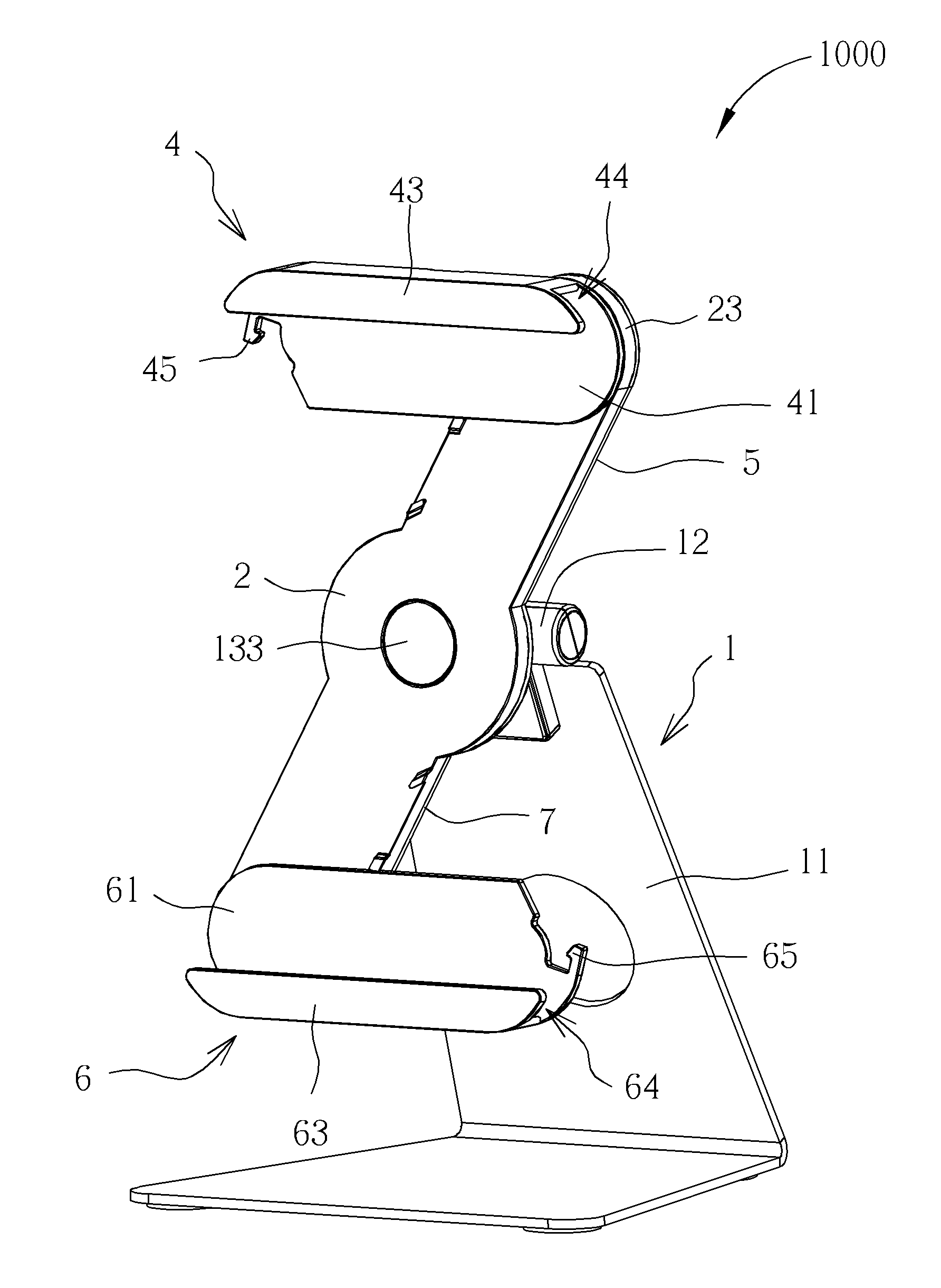
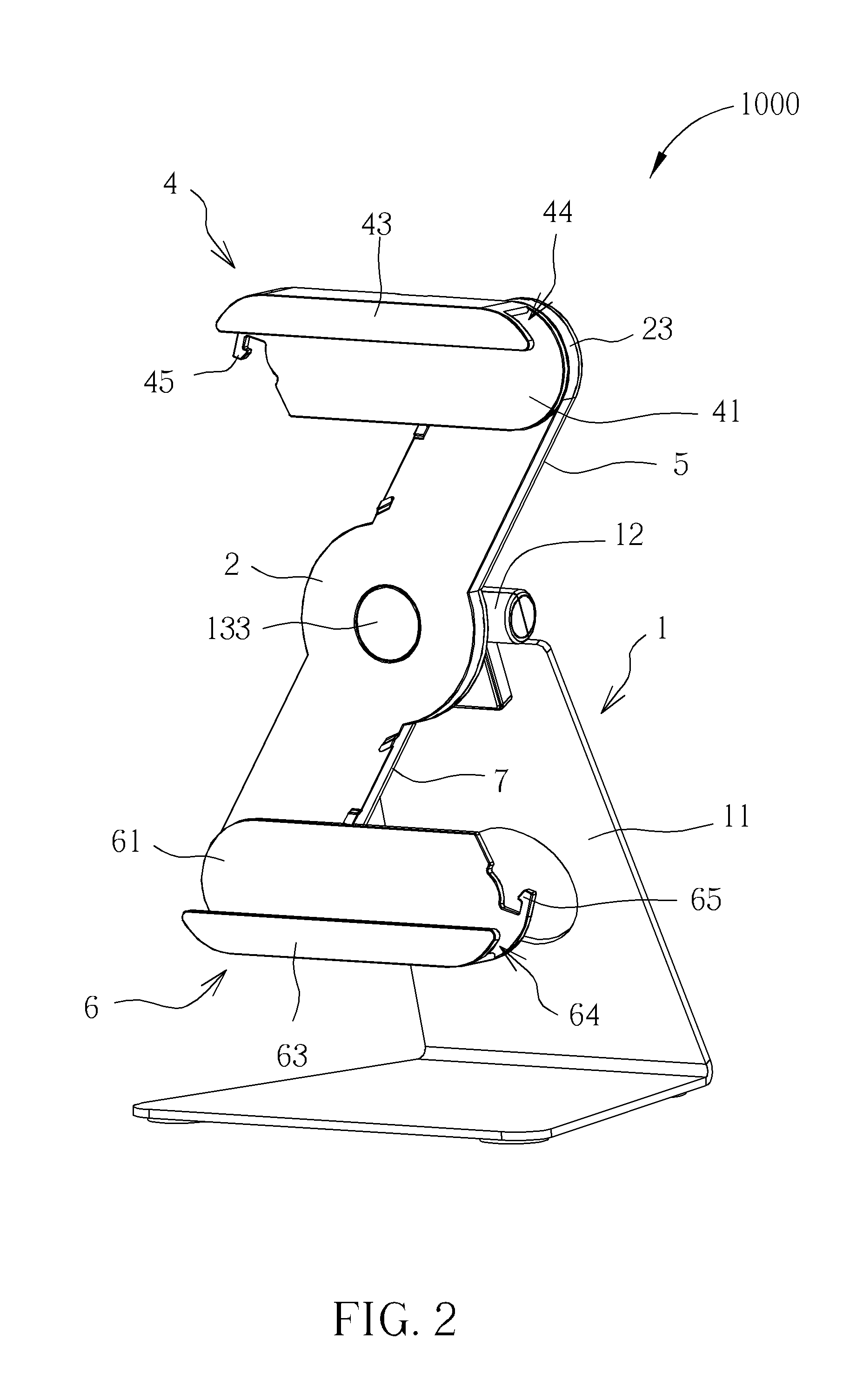
[0035]Please refer to FIG. 2 to FIG. 4. The holding device 1000 includes a frame 1, a rotating arm 2, a driving member 3, a first holding mechanism 4 and a second holding mechanism 5. The rotating arm 2 is pivoted to the frame 1. The driving member 3 drives the rotating arm 2 to rotate, relative to the frame 1, to different positions. The first holding mechanism 4 and the second holding mechanism 5 are installed on two ends of rotating arm 2 respectively.

[0036]The frame 1 includes a frame body 11, a pivot shaft 12 and a connecting assembly 13. In this embodiment, the frame body 11 is a bending-shaped plate for being placed on a support surface, such as a desktop, and thus the holding device 1000 stands on the support surface. The pivot shaft 12 is installed on an end of the frame body 11 far from the support surface. The connecting assembly 13 is used for connecting the pivot shaft 12 with rotating arm 2, so that the rotating arm 2 rotates relative to an axis X of the pivot shaft 12...


PUM


Abstract

A holding device includes a frame, a rotating arm, a first swing arm and a second swing arm. The rotating arm is pivoted to the frame and switchable between a first position and a second position relative to the frame. The first swing arm and the second swing arm are pivoted to the rotating arm and tend to rotate in a rotating direction. When the rotating arm is in the first position with the first swing arm and the second swing arm clamping two long sides of an electronic device, the first swing arm and the second swing arm are spaced at a first distance. When the rotating arm is in the second position with the first swing arm and the second swing arm clamping two short sides of the electronic device, the first swing arm and the second swing arm are spaced at a second distance.

Description

BACKGROUND OF THE INVENTION[0001]1. Field of the Invention[0002]The present invention relates to a holding device, and more particularly, to a holding device capable of generating different holding distances by utilizing rotating mechanism.[0003]2. Description of the Prior Art[0004]Please refer to FIG. 1. FIG. 1 is a diagram of an electronic device holder 9 in the prior art. The electronic device holder 9 includes a rotating unit 91 and a holding unit 92. The holding unit 92 is installed on the rotating unit 91. The holding unit 92 includes a fixing member 921, a secure clamping arm 922 and a movable clamping arm 923. The fixing member 921 is for supporting an electronic device, not shown in figures. The secure clamping arm 922 is fixed on the fixing member 921, and the movable clamping arm 923 is movably disposed on the fixing member 921. The electronic device holder 9 further utilizes a spring 93 for driving the movable clamping arm 923 to recover relative to the secure clamping a...

Claims


Application Information

Patent Timeline
IPC IPC(8): F16M11/06A47F7/00F16M11/18
CPCF16M11/06A47F7/00F16M11/18F16M11/041F16M11/105F16M11/2021F16M13/00
Inventor LIN, HUNG-YU
Owner SYNCMOLD ENTERPRISE CORP
Why Eureka
Try Eureka