Method and Device for Mapping Input Grayscales into Output Luminance

a technology of input luminance and output luminance, which is applied in the direction of instruments, computing, electric digital data processing, etc., can solve the problems of high production cost of display devices, unsatisfactory grayscale representation of display devices to be sensed by human vision, and difficulty in achieving the effect of reducing production costs and reducing production costs

Active Publication Date: 2016-01-21
NOVATEK MICROELECTRONICS CORP
View PDF6 Cites 9 Cited by
  • Summary
  • Abstract
  • Description
  • Claims
  • Application Information

AI Technical Summary

Problems solved by technology

However, the ideal gamma curve shown in FIG. 1 is a nonlinear curve, and thus there is an approximation error when using the linear transformation equation to approximate the nonlinear gamma curve, which may cause unsmooth grayscale representation on the display device to be sensed by human vision.
In order to avoid unsmooth grayscale representation from the display device and improve a display quality of the display device, as many as pinch points are required, a greater hardware area of the lookup table device and a higher production cost of the display device are also required.
In other words, there is a dilemma between the display quality and the production cost, i.e. smooth grayscale representation and the hardware area of the lookup table unit, based on a traditional mapping scheme for mapping the input grayscales into corresponding voltage levels, i.e. the linear interpolation to the linear transformation equation for approximating the nonlinear gamma curve.

Method used


Image

  • Method and Device for Mapping Input Grayscales into Output Luminance
  • Method and Device for Mapping Input Grayscales into Output Luminance
  • Method and Device for Mapping Input Grayscales into Output Luminance

Examples


first embodiment

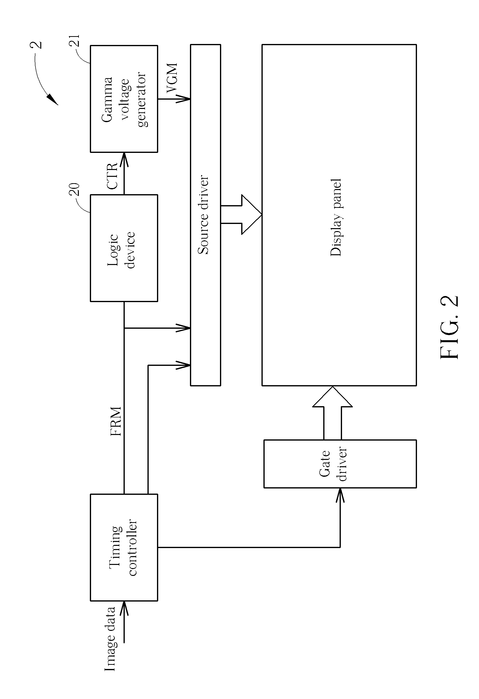
[0031]Please refer to FIG. 3, which is a schematic diagram of the logic device 20 shown in FIG. 2 for mapping the input grayscale X into the corresponding output luminance Y according to the present invention. The logic device 20 includes a lookup table unit 22 and a logic unit 24. The lookup table unit is used for storing a plurality of reference grayscales corresponding to a plurality of reference luminance, respectively.

[0032]The logic unit 24 is coupled to the lookup table unit 22 for selecting reference grayscales X1 and X2, and reference luminance Y1 and Y2 from the plurality of reference grayscales and the plurality of reference luminance according to the input grayscale X indicated by the frame signal FRM. The logic unit 24 then generates the output luminance Y according to the input grayscale X, the reference grayscales X1 and X2 and the reference luminance Y1 and Y2.

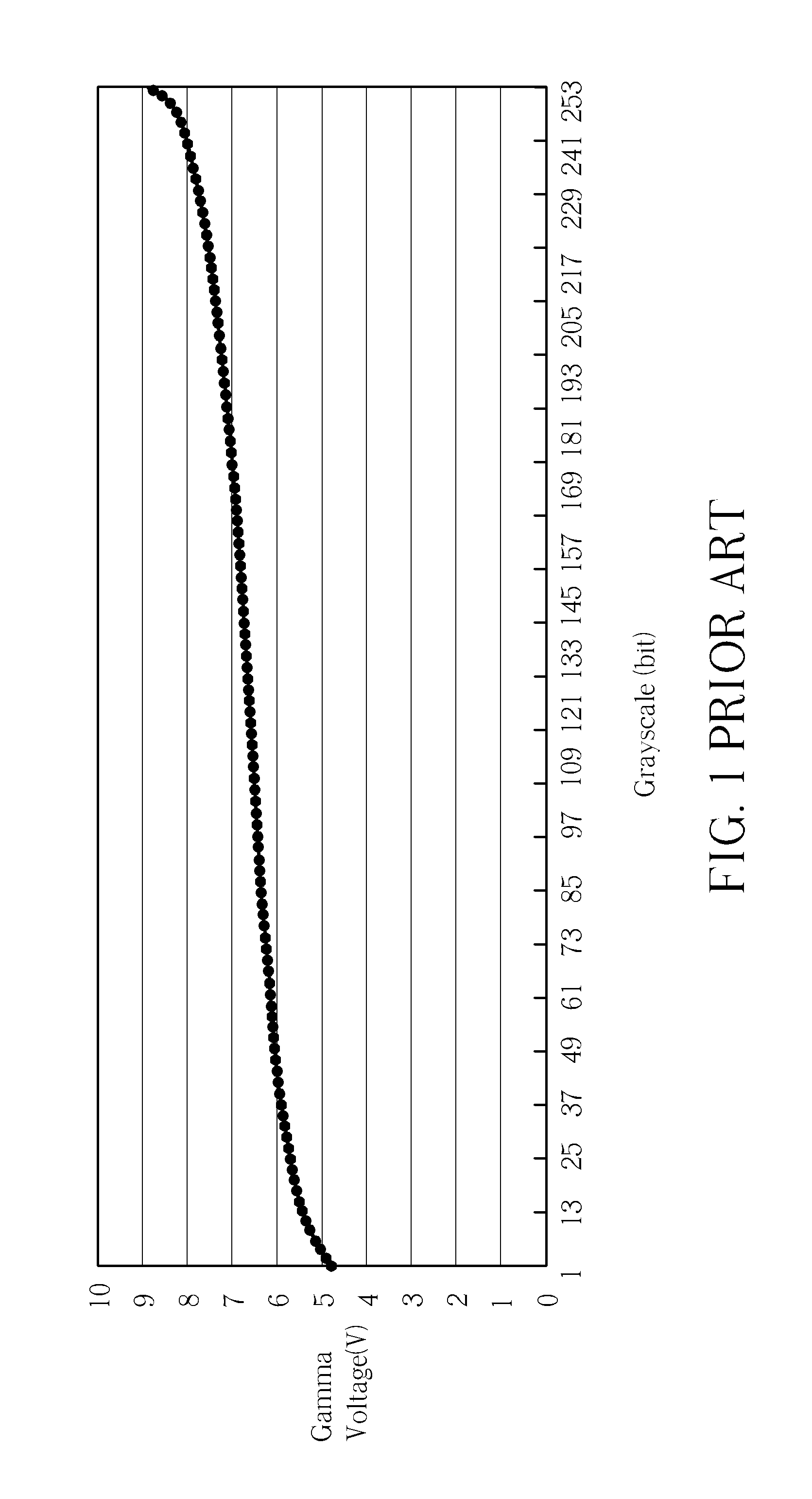
[0033]In detail, please refer to FIG. 4, which illustrates a segment of the gamma curve shown in FIG. 1, whe...

second embodiment

[0059]Please refer to FIG. 7, which is a schematic diagram of a logic device 70 according to the present invention. The logic device 70 can take place of the logic device 20 shown in FIG. 2, and includes a lookup table unit 72, a logic unit 74 and a compensating unit 76. The lookup table unit 72 is used for storing the plurality of pinch points (X1, Y1) to (XN,YN) and a plurality of slope compensating values.

[0060]The logic unit 74 is coupled to the lookup table unit 72 for selecting the reference grayscales X1 and X2, and the reference luminance Y1 and Y2 from the plurality of reference grayscales and the plurality of reference luminance according to the input grayscale X indicated by the frame signal FRM. The logic unit 74 then generates the output luminance Y according to the input grayscale X, the reference grayscales X1 and X2 and the reference luminance Y1 and Y2. The compensating unit 76 is coupled to the logic unit 74 and the lookup table unit 72 for generating a compensated...


PUM


Abstract

A method for mapping an input grayscale into an output luminance includes selecting a first reference grayscale, a first reference luminance, a second reference grayscale and a second reference luminance according to an input grayscale, generating a middle reference grayscale and a middle luminance, replacing a value of the first or second reference grayscale by a value of the middle reference grayscale, and replacing a value of the first or second reference luminance by a value of the middle luminance according to the middle reference grayscale and the input grayscale, and generating an output luminance by computing a linear transformation equation.

Description

BACKGROUND OF THE INVENTION[0001]1. Field of the Invention[0002]The present invention relates to a method and device for mapping input grayscales into output luminance, and more particularly, to a method and device for mapping input grayscales into output luminance by computing a linear transformation equation.[0003]2. Description of the Prior Art[0004]In n-bit color depth display devices, each pixel of the display device has 2̂n grayscales, each of which corresponds to a specific voltage level. In other words, various degrees of bright / dark visual performances are achieved by driving each pixel with 2̂n distinct voltage levels.[0005]Please refer to FIG. 1, which illustrates an ideal gamma curve for mapping input grayscales into distinct voltage levels, respectively. Take an 8-bit color depth display device for example, there are grayscales 1 to 254 corresponding to distinct 254 voltage levels for the ideal gamma curve, wherein grayscales 0 and 255 are respectively pure dark and pur...

Claims


Application Information

Patent Timeline
Patent Type & Authority Applications(United States)
IPC IPC(8): G09G5/10G09G3/36
CPCG09G3/3607G09G5/10G09G2320/0646G09G2320/0626G09G2310/0272G09G3/3696G09G2320/0276G09G2320/0673G09G2360/16
Inventor CHANG, YU-PINDAI, KAI-IHUANG, JIE-JUNGCHUANG, YU-HSINGHUANG, SHIH-HUNG
Owner NOVATEK MICROELECTRONICS CORP
Why Eureka
Try Eureka