Cargo transporter loading assembly

Active Publication Date: 2016-01-28
FLSMIDTH AS
View PDF20 Cites 2 Cited by
  • Summary
  • Abstract
  • Description
  • Claims
  • Application Information

AI Technical Summary

Benefits of technology

This patent describes a cover for the boom of a cargo transporter that prevents wind and rain from getting inside the area below the boom. The cover extends over the boom and the sides, creating a shield. The cover is positioned close to the ground to better protect the boom and head part. Additionally, the patent discusses the design of the funnel section, which is curved along its length to improve its ability to reach the corners of the cargo hold. The technical effect of this patent is to provide better protection and access for the cargo transporter during inclement weather and to improve the efficiency of the funnel section in reaching the corners of the cargo hold.

Problems solved by technology

Further, the inability to load these materials during inclement weather causes delays in shipping the materials to their intended destination.

Method used


Image

  • Cargo transporter loading assembly
  • Cargo transporter loading assembly
  • Cargo transporter loading assembly

Examples


Embodiment Construction

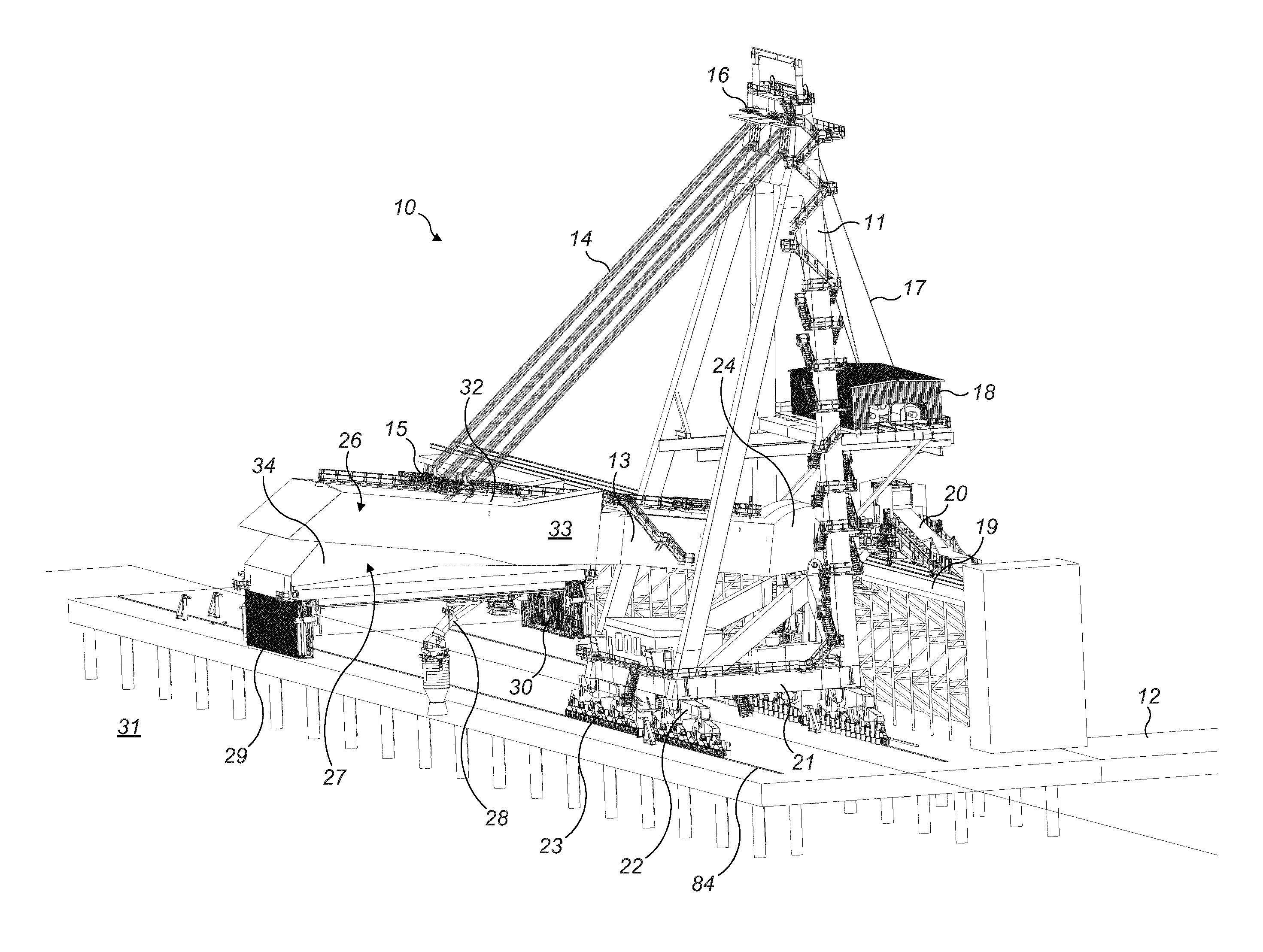
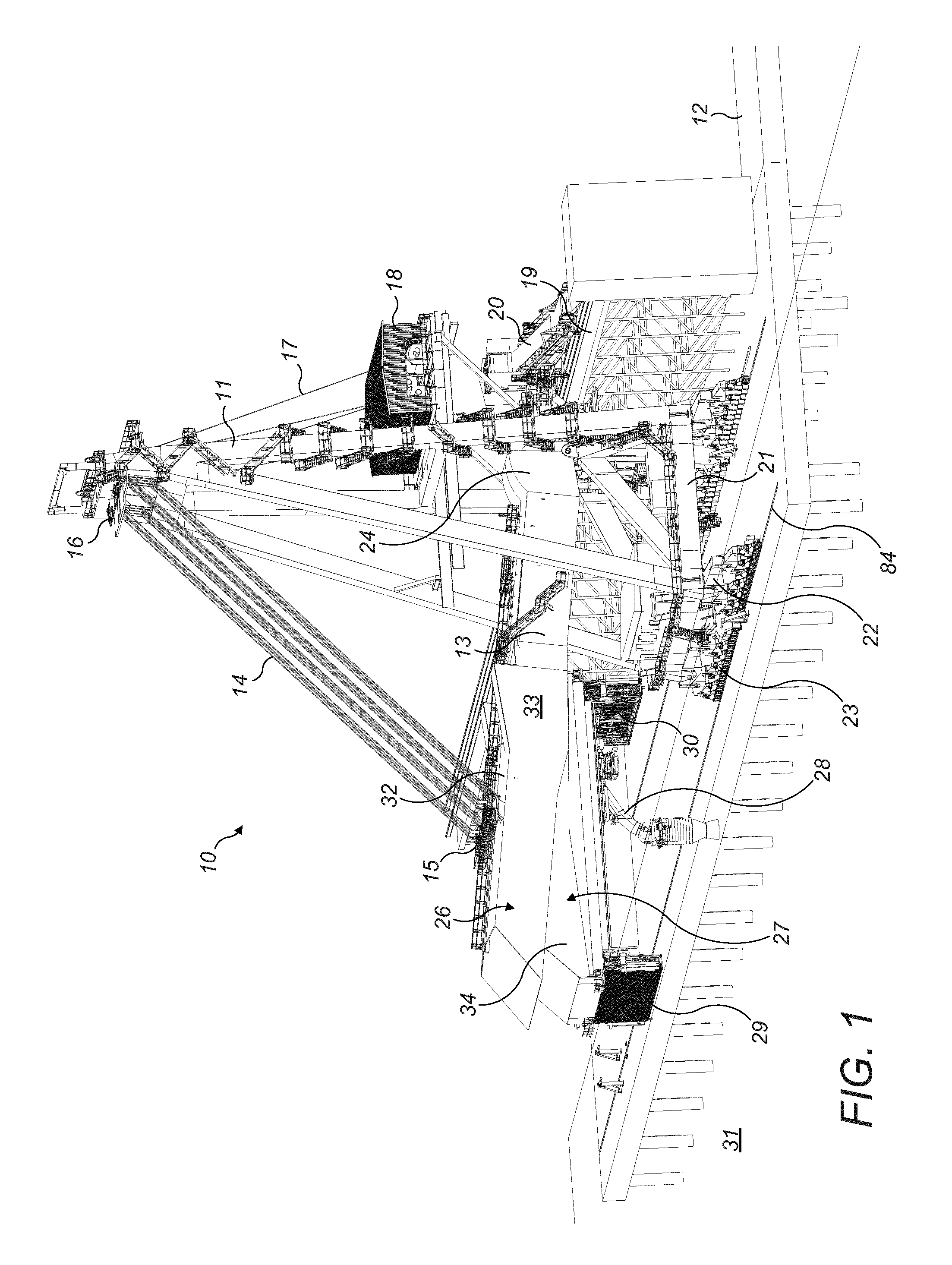
[0046]Referring to FIGS. 1 to 8, a loading assembly 10 comprises a mainframe 11 moveably mounted upon a support structure in the form of a pier 12 suspended above the sea 31. Frame 11 is upstanding and comprises a generally A-frame configuration. A lower or base region 21 of frame 11 mounts a plurality of wheeled bogies 22 each carrying a plurality of wheels 23 to enable frame 11 to move linearly along a pair of parallel tracks 84 extending along pier 12. Frame 11 is configured to move linearly along pier 12 with respect to a gantry 19 that extends linearly to a rearward side of tracks 84. Gantry 19 supports at its upper linear end a shuttle car 20 that carries a conveyor to transport bulk material from a stock pile at pier 12 onto the loading assembly 10.

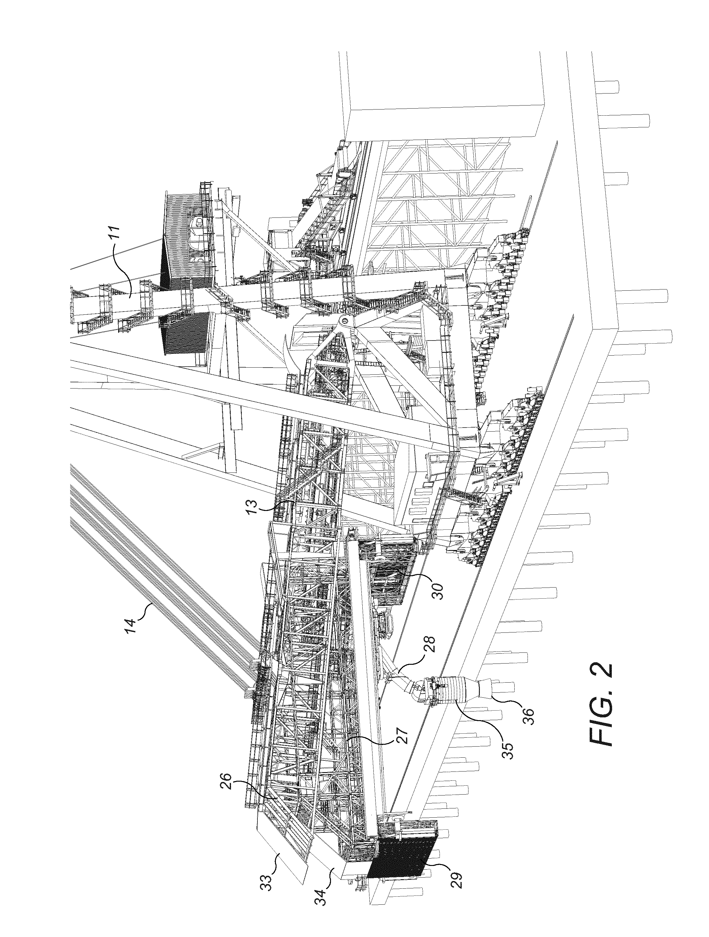
[0047]The assembly 10 further comprises a boom 13 formed from an interconnected open truss structure having a proximal end 24 and a distal end 26. Proximal end 24 is pivotally mounted at a mid-height region of frame 11 via pivot mo...


PUM


Abstract

A cargo transporter loading assembly for loading bulk material onto a cargo transporter. The assembly includes a frame carrying a pivotally mounted boom. A distal end of the boom carries a head part encased by a cover and configured to prevent wind and rain ingress into the region between the boom and a cargo hold of a cargo transporter during bulk material loading.

Description

FIELD OF INVENTION[0001]The present invention relates to a cargo transporter loading assembly for loading bulk material into a cargo transporter and in particular, although not exclusively, to a ship loader assembly.BACKGROUND ART[0002]It is common practice and procedure to avoid loading moisture-sensitive materials onto cargo ships during inclement weather such as rain and wind egress as they may become water damaged or displaced. Moisture sensitive materials include, but are not limited to, bulk foods such as grain and rice and other materials such as pot ash and fertilizers. Further, the inability to load these materials during inclement weather causes delays in shipping the materials to their intended destination.[0003]Example ship loading systems with conventional loading assemblies are described in U.S. Pat. No. 3,388,818A; U.S. Pat. No. 4,065,002A; GB 1536303A; U.S. Pat. No. 5,193,965A; EP 980328B1; WO 2005 / 123494A1; US 2007 / 0217895A1.[0004]Accordingly, what is required is a ...

Claims


Application Information

Patent Timeline
IPC IPC(8): B63B27/28
CPCB63B27/28B65G67/606B66C19/00B65G67/60B65G67/603
Inventor PLETZ, RUDOLFVORAUER, JOACHIMHOCHEGGER, FRANK
Owner FLSMIDTH AS
Why Eureka
Try Eureka