
Grade Control Cleanup Pass Using Cost Optimization

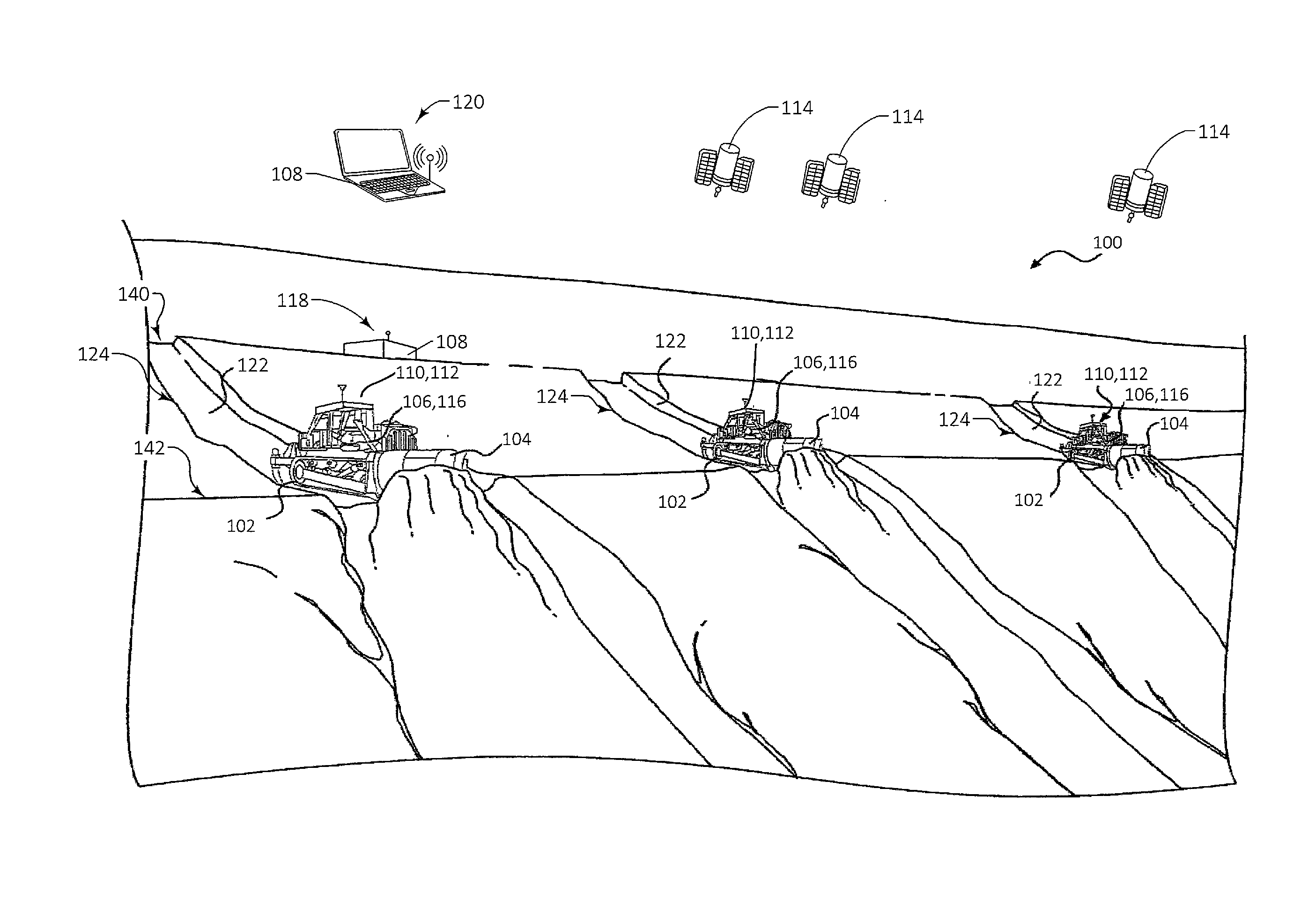
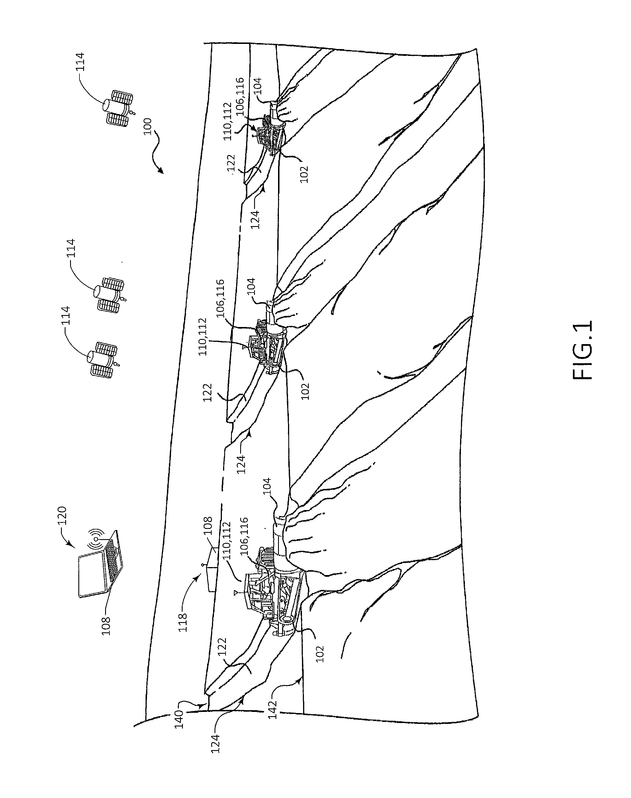
a cleanup pass and control pass technology, applied in mechanical machines/dredgers, analogue processes for specific applications, instruments, etc., can solve problems such as unwanted deviations from planned profiles, cut and carry passes may deviate from planned profiles, and conventional processes are limited to profiles formed using s-shaped gaussian curves. , to achieve the effect of minimizing cost value, minimizing cost value, and minimizing cost valu

Inactive Publication Date: 2016-02-11
CATERPILLAR INC
View PDF0 Cites 18 Cited by
  • Summary
  • Abstract
  • Description
  • Claims
  • Application Information

AI Technical Summary

Benefits of technology

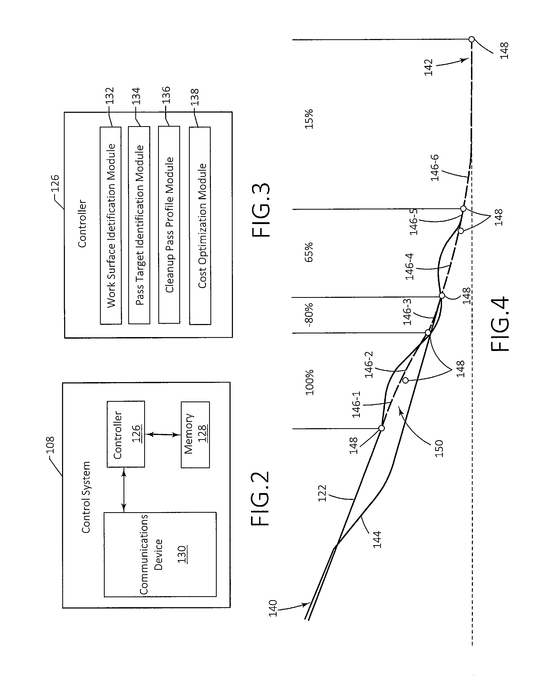
This patent text describes a computer-implemented method and control system for determining a cleanup pass profile for a machine implement. The method involves identifying a pass target, determining a plurality of primatives of a cleanup pass profile, and minimizing the cost value associated with moving the machine implement along the cleanup pass profile by adjusting volume constraints associated with the primitives. The technical effects of this patent include improving the efficiency and accuracy of cleaning machines, reducing labor costs, and minimizing damage to works surfaces.

Problems solved by technology

However, autonomous carry passes often adjust the blade height while in the blade-carry region which can result in unwanted deviations from the planned profile.
In actual practice, however, cut and carry passes may deviate from the planned profile due to factors such as hard soil, insufficient ripping, degradations in position estimation, hump building, large rocks, boulders or other embedded obstacles, and the like.
For instance, conventional processes are limited to profiles formed using S-shaped Gaussian curves, which cannot sufficiently adapt to negative volumes or valleys in the terrain that dip below the target profile, bumps in the terrain that extend above the pass target, or the like.

Method used


Image

  • Grade Control Cleanup Pass Using Cost Optimization
  • Grade Control Cleanup Pass Using Cost Optimization
  • Grade Control Cleanup Pass Using Cost Optimization

Examples


Embodiment Construction

[0015]Although the following sets forth a detailed description of numerous different embodiments, it should be understood that the legal scope of protection is defined by the words of the claims set forth at the end of this patent. The detailed description is to be construed as exemplary only and does not describe every possible embodiment since describing every possible embodiment would be impractical, if not impossible. Numerous alternative embodiments could be implemented, using either current technology or technology developed after the filing date of this patent, which would still fall within the scope of the claims defining the scope of protection.

[0016]It should also be understood that, unless a term is expressly defined herein, there is no intent to limit the meaning of that term, either expressly or by implication, beyond its plain or ordinary meaning, and such term should not be interpreted to be limited in scope based on any statement made in any section of this patent (o...


PUM


Abstract

A computer-implemented method for determining a cleanup pass profile for a machine implement is provided. The method may include identifying a pass target extending from a first end to a second end along a work surface, determining a plurality of primitives of a cleanup pass profile extending between the first end and the second end where each primitive may be defined based at least partially on volume constraints, determining a cost value associated with moving the machine implement along the cleanup pass profile based on an optimization cost function, and adjusting the volume constraints associated with one or more of the primitives to minimize the cost value.

Description

TECHNICAL FIELD[0001]The present disclosure relates generally to controlling machines, and more particularly, to systems and methods for determining cleanup pass profiles for semi-autonomous and autonomous machines using cost optimization.BACKGROUND[0002]Machines such as, for example, track-type tractors, dozers, motor graders, wheel loaders, and the like, are used to perform a variety of tasks. For example, these machines may be used to move material and / or alter work surfaces at a worksite. The machines may be manned machines, but may also be autonomous or semi-autonomous vehicles that perform these tasks in response to commands remotely or locally generated as part of a work plan for the machines. The machines may receive instructions in accordance with the work plan to perform operations, including digging, loosening, carrying, and any other manipulation of materials at the worksite.[0003]It may be desirable to ensure that the machines perform these operations such that the mate...

Claims


Application Information

Patent Timeline
IPC IPC(8): E02F3/84E02F9/20
CPCE02F9/2045E02F3/84E02F9/262
Inventor KONTZ, MATTHEW E.TAYLOR, MICHAEL A.STRATTON, KENNETH L.
Owner CATERPILLAR INC
Learn More