

Inertial separator
- Summary
- Abstract
- Description
- Claims
- Application Information
AI Technical Summary
Benefits of technology
Problems solved by technology
Method used
Image

Examples
third embodiment
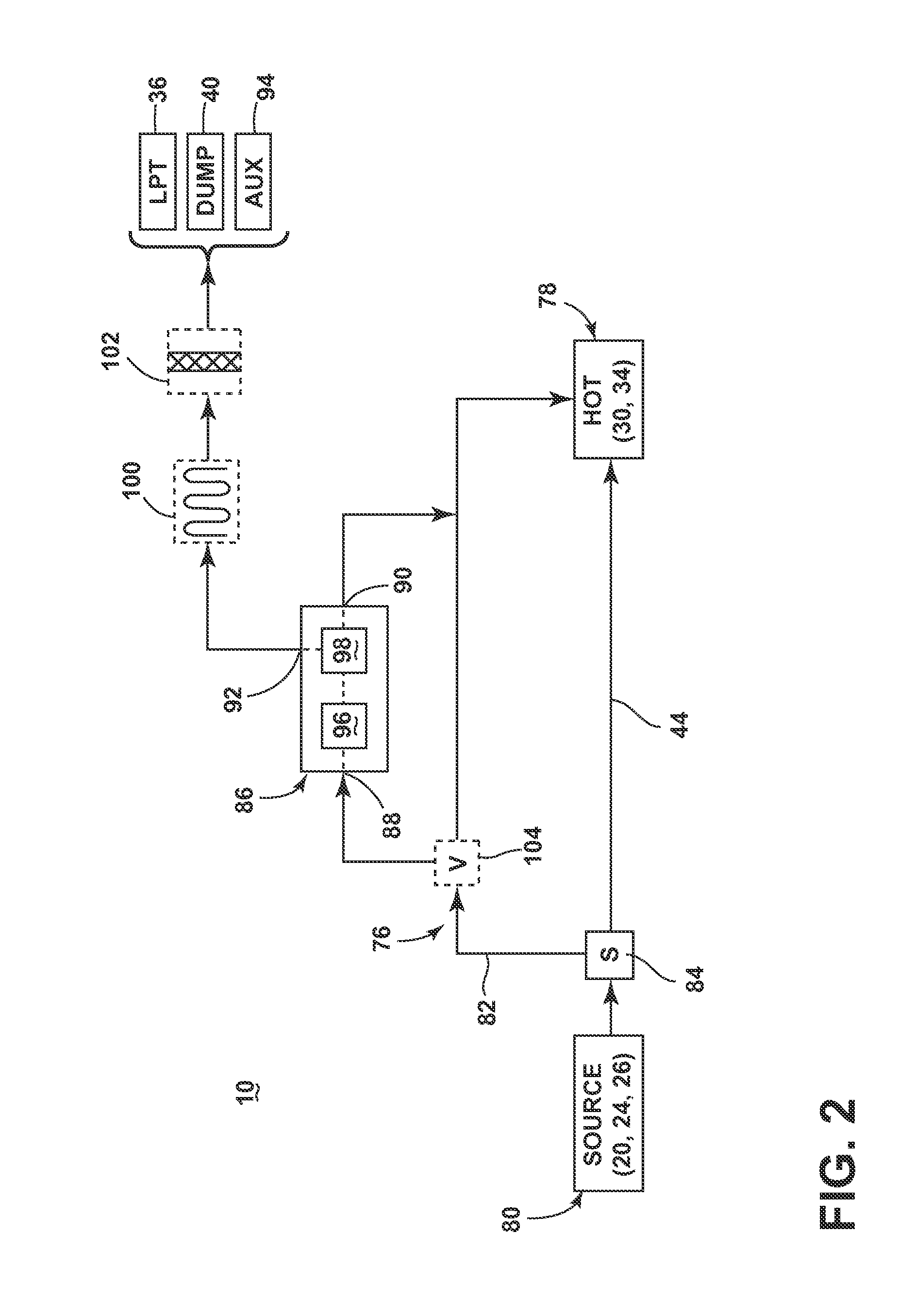
[0060]FIG. 3 shows one specific configuration of the bypass cooling circuit 76 in which the reduced-particle stream can be provided to the HP turbine 34, according to a The bypass cooling circuit 76 can further include an inducer section 106 for injecting the reduced-particle stream into the HP turbine 34. In a typical engine 10, the inducer section 106 accelerates the cooling fluid stream and also turns the cooling fluid stream from a substantially axial direction parallel to the centerline 12 of the engine 10 to a direction generally tangential to the face of the blades 68, so as to tangentially inject the cooling fluid stream into the rotating blades 68 at a rotational or tangential speed and direction substantially equal to that of the blades 68. By “generally tangential”, the cooling fluid stream may be oriented at a slightly shallow angle with respect to a true tangential direction.
[0061]In the present embodiment, the inducer section 106 can form a portion of the bypass condu...
fourth embodiment
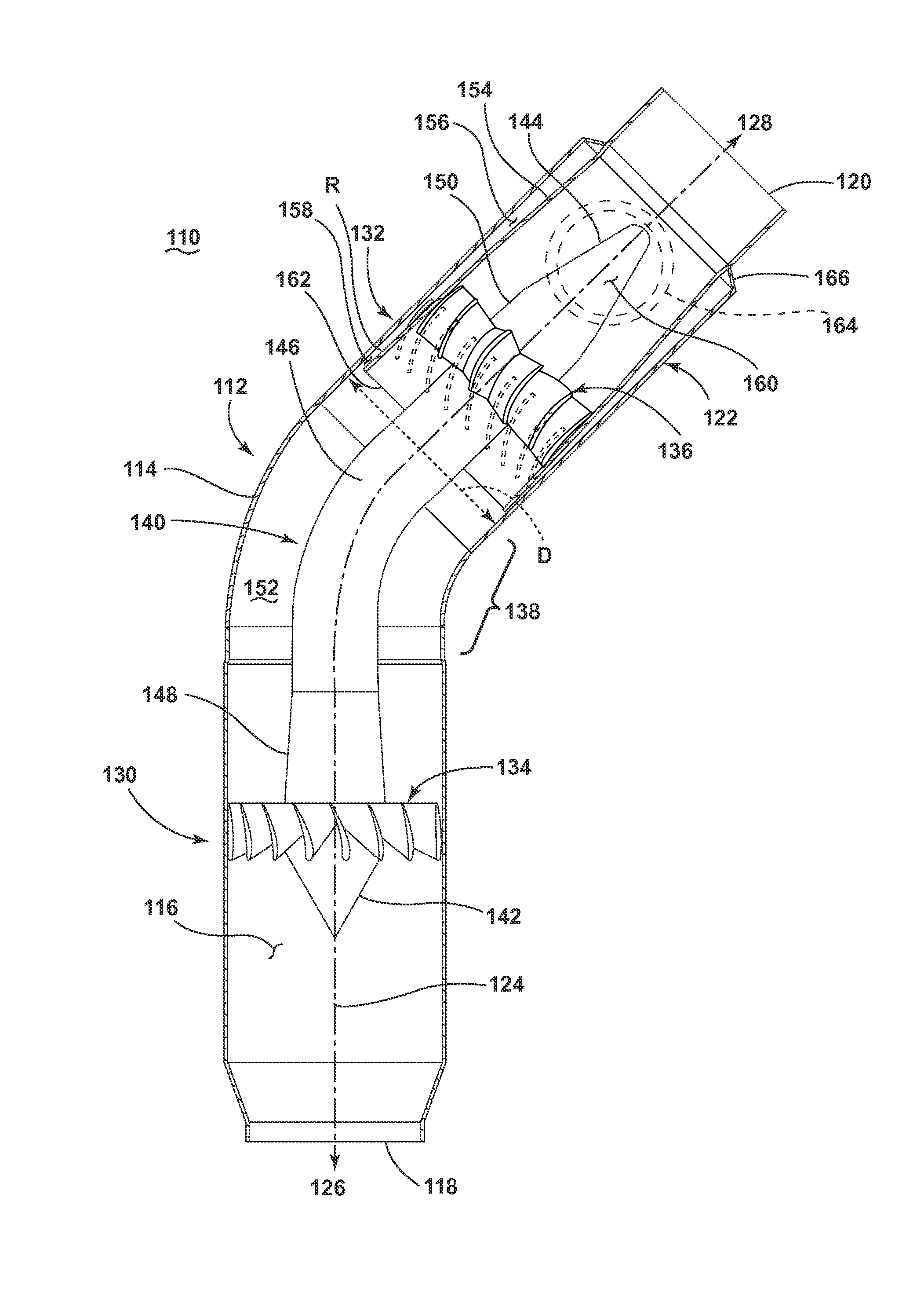
[0065]FIG. 4 is a cross-sectional view showing a centrifugal separator 110 for removing particles from a fluid stream according to a The centrifugal separator 110 includes a body 112 having a wall 114 defining a through passage 116, with a separator inlet 118 which receives a fluid stream, a separator outlet 120 through which a reduced-particle stream is passed, and a particle outlet 122 through which a concentrated-particle stream is passed. The through passage 116 defines a centerline 124 of the centrifugal separator 110, with the centerline 124 generally defining an upstream direction 126 and downstream direction 128 with respect to the centrifugal separator 110.
[0066]The centrifugal separator 110 further includes a particle concentrator 130 and a flow splitter 132. The particle concentrator 130 of the illustrated embodiment includes an angular velocity increaser 134 provided within the through passage 116, downstream of the separator inlet 118, which is configured to impart an ...
fifth embodiment
[0088]FIG. 10 is a cross-sectional view showing a modified version of a centrifugal separator 110′ in which elements in common with the centrifugal separator 110 of FIG. 4 are referred to by the same reference numerals bearing a prime (′) symbol. The centrifugal separator 110′ differs from the centrifugal separator 110 of FIG. 4 by including a non-continuous center body 192, which is typically easier to manufacture and assemble, along with weighing less and having lower costs. The non-continuous center body 192 can be provided within the through passage 116′, spaced from the annular wall 114′, and can extend axially along the centerline 124′ of the centrifugal separator 110′. In the illustrated embodiment, the center body 192 extends non-continuously between, and beyond, the angular velocity increaser 134′ and the angular velocity decreaser 136′.
[0089]The non-continuous center body 192 includes leading body 194 and a trailing body 196 which is downstream of and separate from the le...
PUM
| Property | Measurement | Unit |
|---|---|---|
| Angle | aaaaa | aaaaa |
| Angle | aaaaa | aaaaa |
| Angle | aaaaa | aaaaa |
Abstract
Description
Claims
Application Information