Fitting system for a vehicle seat and vehicle seat

a technology for vehicle seats and fittings, which is applied in the direction of vehicle components, vehicle arrangements, movable seats, etc., can solve the problems of difficult to insert the first spring end into the fitting holder, and is not possible to transpose, so as to avoid unintentional installation errors, simple manner, and low probability of error

Active Publication Date: 2016-02-18
KEIPER SEATING MECHANISMS CO LTD
View PDF3 Cites 5 Cited by
  • Summary
  • Abstract
  • Description
  • Claims
  • Application Information

AI Technical Summary

Benefits of technology

[0006]The invention is based on an object of improving a fitting system of the type mentioned at the beginning, in particular of facilitating the installation of the stop module on the fitting and of avoiding unintentional installation errors. In addition, a vehicle seat which can be fitted in a simple manner and with little probability of error is intended to be provided.
[0009]The spring end arranged outside the stop module is preferably fastened to a spring holder of a seat section adapter of the seat section, in particular is inserted or hooked into said spring holder. Cost-effective and easily fittable fastening of the spring can thereby be provided.
[0010]The stop module is formed separately from the hand lever. The hand lever can therefore be connected to the stop module during the installation sequence following the fastening of the spring end to the spring holder of the seat section adapter. It is thereby possible to check the correct installation of the spring before the hand lever is connected to the stop module and possibly conceals the view of the spring end. If different operating elements, for example of differing shape and / or differing color, are used for different vehicle seats, the same stop modules can always be used because of the separate formation of hand lever and stop module. Only the operating elements themselves have to be configured individually, which reduces costs, in particular tool costs.
[0011]Axial securing of the spring end in a hole-shaped spring holder can be effectively achieved by the spring end enclosing a small angle of preferably 2° to 15° with a parallel to the rotational axis of the fitting.
[0012]The stop module contains only precisely one hole for the hooking in of the other of the two spring ends, and therefore hooking into a hole not provided for this purpose is avoided. An in particular peripheral rounding of a transition region between the cylindrical wall of said hole and a bottom of the housing of the stop module facilitates the insertion of the other of the two spring ends and avoids a collision with the bending radius of the return spring.
[0018]The first function is a precondition for the second function, specifically safeguarding against misuse, in which the transmission of torque is interrupted by the hand lever and one of the fitting parts being brought into relative abutment so that the torque is applied to the said fitting part, that is to say is ineffective. As a result, the internal components of the fitting are protected. This is especially important for rotation in the locking direction because the internal components of the fitting then already occupy their end position and further force action by the transmission rod would directly lead to damage. The second function of the stop module as a safeguard against misuse can also however be extended to the extent that the stop module also becomes effective if the fitting is unlocked and the transmission rod is further rotated into the unlocking direction. The stop module then limits the angular range for the operation of the hand lever.

Problems solved by technology

This makes it difficult to insert the first spring end into a holder of the fitting.
The first operating element and the second operating element significantly differ in shape from each other, and therefore it is not possible for transpositions to occur when installing the operating elements on the vehicle seat.

Method used


Image

  • Fitting system for a vehicle seat and vehicle seat
  • Fitting system for a vehicle seat and vehicle seat
  • Fitting system for a vehicle seat and vehicle seat

Examples


Embodiment Construction

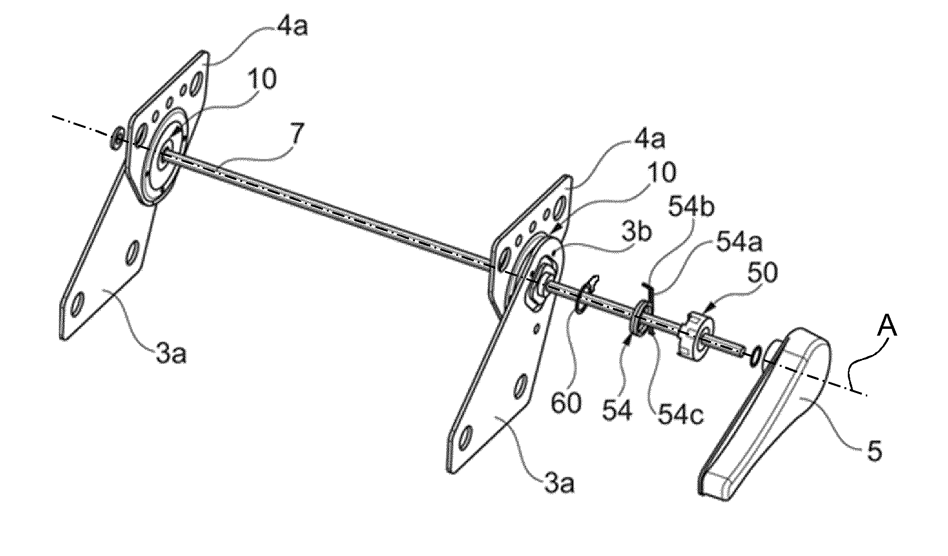
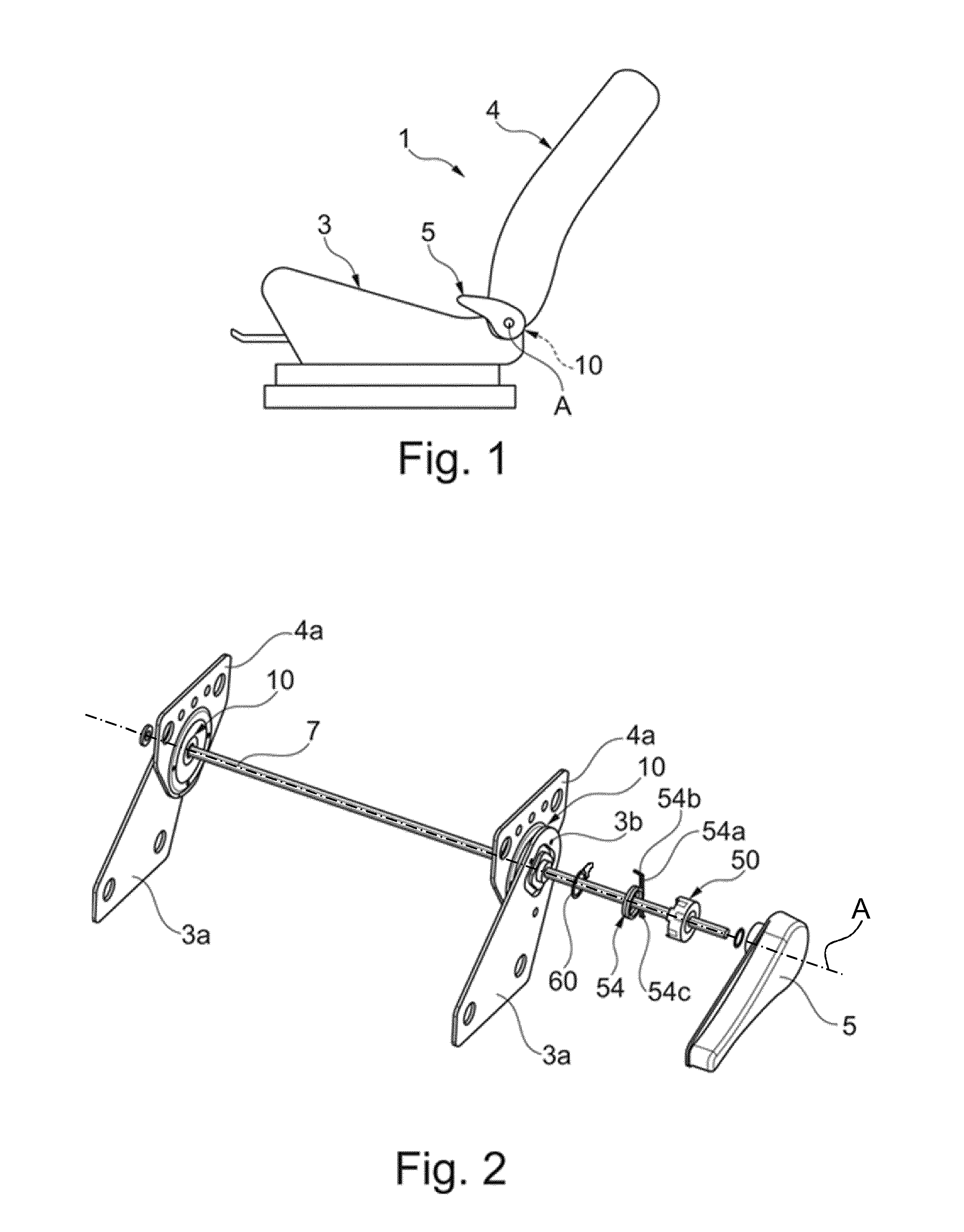
[0045]A vehicle seat 1 for a motor vehicle has a seat section 3 and a backrest 4 which is adjustable in its inclination relative to the seat section 3. For inclination adjustment of the backrest 4, a transmission rod 7, which is arranged horizontally in the transition region between seat section 3 and backrest 4, is rotated manually, for example by means of a hand lever 5. The transmission rod 7 engages in a respective fitting 10 on both sides of the vehicle seat 1. The transmission rod 7 defines the applied direction details of a cylindrical coordinate system, in particular the radial and the axial direction.

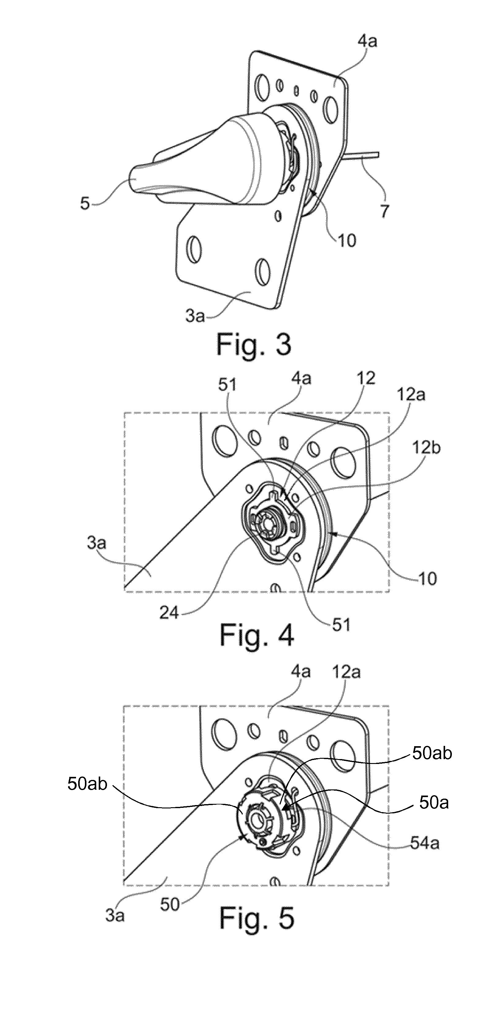
[0046]The fitting 10 is designed as a locking fitting in which a first fitting part 11 and a second fitting part 12 are lockable to each other and, after being unlocked, are rotatable relative to each other about an axis A (aligned with the transmission rod 7), as described, for example, in DE 10 2006 015 560 B3.

[0047]The two fitting parts 11 and 12 can be inscribed in each cas...


PUM


Abstract

A vehicle seat fitting system includes a fitting (10) with a first and second fitting part (11, (12) to lock and rotate about an axis (A), a transfer rod which unlocks the fitting and a hand lever (5), which rotates the transfer rod to unlock the fitting. A stop module (50) is supported on the fitting to rotate about the axis and stop the hand lever and one of the fitting parts in relation to each other in a one rotational direction. The stop module has a stop (50b) and the one fitting part has a counter stop (51) that define a rotational angular range. A restoring spring (54) with spring ends (54b, 54c) preloads the stop (50b) in the direction of the counter stop. One of the spring ends is fastened to a spring mount (3b) arranged outside of the stop module in a radial direction.

Description

CROSS REFERENCE TO RELATED APPLICATIONS[0001]This application is a United States National Phase Application of International Application PCT / EP2014 / 056521 filed Apr. 1, 2014 and claims the benefit of priority under 35 U.S.C. §119 of German Patent Applications 10 2013 206 096.3 filed Apr. 5, 2013 and 10 2013 210 688.2 filed Jun. 7, 2013 the entire contents of which are incorporated herein by reference.FIELD OF THE INVENTION[0002]The invention relates to a fitting system for a vehicle seat with at least one fitting which has a first fitting part and a second fitting part, which are lockable to each other and are rotatable relative to each other about an axis, a transmission rod, the rotation of which unlocks the fitting, a hand lever, the actuation of which at least indirectly rotates the transmission rod in order to unlock the fitting, a stop module which is mounted on the fitting so as to be rotatable about the axis, is formed separately from the hand lever and on the one hand is fu...

Claims


Application Information

Patent Timeline
Patent Type & Authority Applications(United States)
IPC IPC(8): B60N2/22
CPCB60N2/22B60N2/2227B60N2/236B60N2/2356
Inventor ASSMANN, UWE
Owner KEIPER SEATING MECHANISMS CO LTD
Why Eureka
Try Eureka