Apparatus for spectrum and intensity profile characterization of a beam, use thereof and method thereof

a spectrum and intensity profile and beam technology, applied in the field of devices, use and characterization of beams, can solve the problems of reducing the quality of detected spectrum, requiring two independent detectors, and requiring a large investment. the effect of reducing the quality of the detected spectrum

Active Publication Date: 2021-02-09
FYZIKALNI USTAV AV CR V V I
View PDF10 Cites 0 Cited by
  • Summary
  • Abstract
  • Description
  • Claims
  • Application Information

AI Technical Summary

Benefits of technology

[0021]In a preferred embodiment, the reflective element is a plane mirror or any suitable reflectance material capable of reflecting radiant energy of the incident beam. Which serves to reflect the angularly dispersed components of the beam onto a fixed detector. In another preferred embodiment, the mirror is covered with a special layer increasing its reflectivity within a given spectral range for given beam.
[0023]The fixed detector is used to detect both the spectral characteristics of the beam and to characterize the beam intensity profile. In a preferred embodiment, the detector is a CCD-based X-ray camera or other suitable type of available or specially developed detector of a given type of beam. This detector is positioned on the axis of the incoming beam. The detector used to characterization both, the spectral and intensity profile, positioned on the beam axis provides technical effect of calibration of single one detector. No method of cross-calibration is thus needed in order to detect both, the spectrum and intensity profile of the beam. Besides that, single detector provides a smaller probability of error during measurement.
[0027]1) Spectrometric mode (FIG. 1): The diffractive element located on the beam axis (with the help of movement A) images the radiation source and spectrally disperses the beam coming from radiation source. The reflective element serves to direct the beams to the detector and to alter the spectral range of the detected radiation (via C translation). A diffractive element is mechanically connected to a beam block that serves to block a portion of the direct beam that would otherwise impact on the detector and reduce the quality of the detected spectrum. The translation of the diffractive element along the incoming beam direction (shift in direction B) allows focusing the source images in a given spectral range on detector surface.

Problems solved by technology

Spectrometers for characterization of spectrum ranging from the VUV to soft X-rays are well known, but none of them allows monitoring an incident beam profile, so the spectrometer is usually supplemented or replaced by another detector designed to measure the beam intensity profile.
The use of two independent detectors is costly and can cause complications in evaluating acquired data since accurate calibration of detectors can be quite challenging.
This concept of the spectrometer is known to those skilled in the art, but does not address the question of monitoring the radiation intensity profile.
Another disadvantage of such a configuration is the need to divide the beam into two optical paths, wherein only a portion of the total beam intensity continues into the energy sensor and the second part is used for spectral analysis purposes.

Method used


Image

  • Apparatus for spectrum and intensity profile characterization of a beam, use thereof and method thereof
  • Apparatus for spectrum and intensity profile characterization of a beam, use thereof and method thereof

Examples


Embodiment Construction

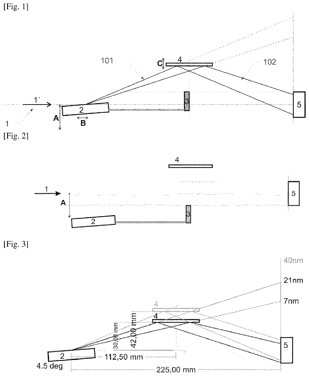
[0046]An apparatus according to present invention was constructed to determine the spectrum and the intensity profile of the beam 1 of high harmonic frequencies generated by the interaction of the intense femtosecond laser with the gaseous environment in the research center PALS (joint laboratory of Institute of Physics AS CR and Institute of Plasma Physics AS CR).

[0047]FIG. 3 represents a sketch of the apparatus according to the invention comprising:[0048]a diffractive element 2 diffracting the beam 1 into spectral components 101;[0049]a beam block 3 attached to the diffractive element 2;[0050]a reflective element 4 configured to reflect the spectral components 101 diffracted on the diffractive element 2;[0051]a fixed detector 5 positioned on the axis of the incoming beam 1 and configured to receive reflected spectral components 102 from the reflective element 4; and[0052]a device for translation of the beam block 3 and the diffractive element 2; wherein the device is capable of mo...


PUM

PropertyMeasurementUnit
incident angleaaaaaaaaaa
wavelengthaaaaaaaaaa
incidence angleaaaaaaaaaa

Abstract

The present invention concerns an apparatus for spectral and intensity profile characterization comprising: a diffractive element; a beam block (3) attached to the diffractive element, the beam block (3) being positioned so as to block the passage of the direct incoming beam (1) which is not incident on the diffractive element; a device for translation of the beam block (3) and the diffractive element; reflective element (4); fixed detector (5) positioned on the axis of the incoming beam (1). The invention also concerns use and a method thereof. Such a compact system provides application in the field of spectrometry and diagnostics of the beam intensity profile, especially in the area of XUV and soft X-rays.

Description

[0001]This application is the continuation of International Application No. PCT / CZ2017 / 050050, filed Oct. 21, 2017, which claims the benefit of Czech Patent Application No. PV 2016-661, filed 21 Oct. 2016, the entire contents of which are hereby incorporated by reference.TECHNICAL FIELD[0002]The present invention relates to a device, use and a method of characterization of a beam, preferably VUV, XUV, X-ray and visible. The present invention provides means to determine spectral and intensity profile characterization of the beam.BACKGROUND ART[0003]Spectrometers for characterization of spectrum ranging from the VUV to soft X-rays are well known, but none of them allows monitoring an incident beam profile, so the spectrometer is usually supplemented or replaced by another detector designed to measure the beam intensity profile. The use of two independent detectors is costly and can cause complications in evaluating acquired data since accurate calibration of detectors can be quite cha...

Claims


Application Information

Patent Timeline
Patent Type & Authority Patents(United States)
IPC IPC(8): G01J3/28G01J1/42G01J3/02G01J3/18G01N23/207
CPCG01J1/4257G01J1/429G01J3/021G01J3/0237G01J3/0262G01J3/0289G01J3/18G01N23/2076G01J2003/1847G01N2223/1016
Inventor NEJDL, JAROSLAV
Owner FYZIKALNI USTAV AV CR V V I
Why Eureka
Try Eureka