Plate microvalve with improved sealing mechanism

a technology of micro-valve and sealing mechanism, which is applied in the direction of valve arrangement, slide valve, mechanical apparatus, etc., can solve the problems of inability to move freely between the displaceable member and the displaceable member, and inability to prevent the displaceable member from jamming

Active Publication Date: 2016-02-18
DUNAN MICROSTAQ
View PDF7 Cites 3 Cited by
  • Summary
  • Abstract
  • Description
  • Claims
  • Application Information

AI Technical Summary

Benefits of technology

[0007]This invention relates to an improved structure for a microvalve that resists interference with the free movement of a displaceable member of the microvalve that might otherwise result from the presence of particulate contaminants contained in the fluid flowing therethrough. The microvalve includes a first plate having a surface, a recessed region provided within the surface, a fluid port provided within the recessed region, and a sealing structure extending about the fluid port. A second plate defines a non-movable portion and a movable portion, a surface of the non-movable portion abutting the surface of the first plate, the non-movable portion having first and second openings formed therethrough. The movable portion is formed within the first opening and has an axis, the movable portion defining a displaceable member connected to the non-movable portion by a convoluted spring formed in a second opening. The displaceable member is slidingly and axially movable within the first opening between a closed position, wherein the displaceable member cooperates with the sealing structure to prevent fluid communication through the fluid port, and an opened position, wherein the displaceable member does not cooperate with at least a portion of the sealing structure to prevent fluid communication through the fluid port.

Problems solved by technology

However, it has been found that when this conventional microvalve structure is used to control the flow of fluid containing solid particles (such as particulate contaminants that may be contained within the fluid), such particles may become jammed between the displaceable member and the adjacent portions of the microvalve that define the closed internal cavity.
The jamming of such particles can, in some instances, undesirably interfere with the free movement of the displaceable member between the closed and opened positions.

Method used


Image

  • Plate microvalve with improved sealing mechanism
  • Plate microvalve with improved sealing mechanism
  • Plate microvalve with improved sealing mechanism

Examples


Embodiment Construction

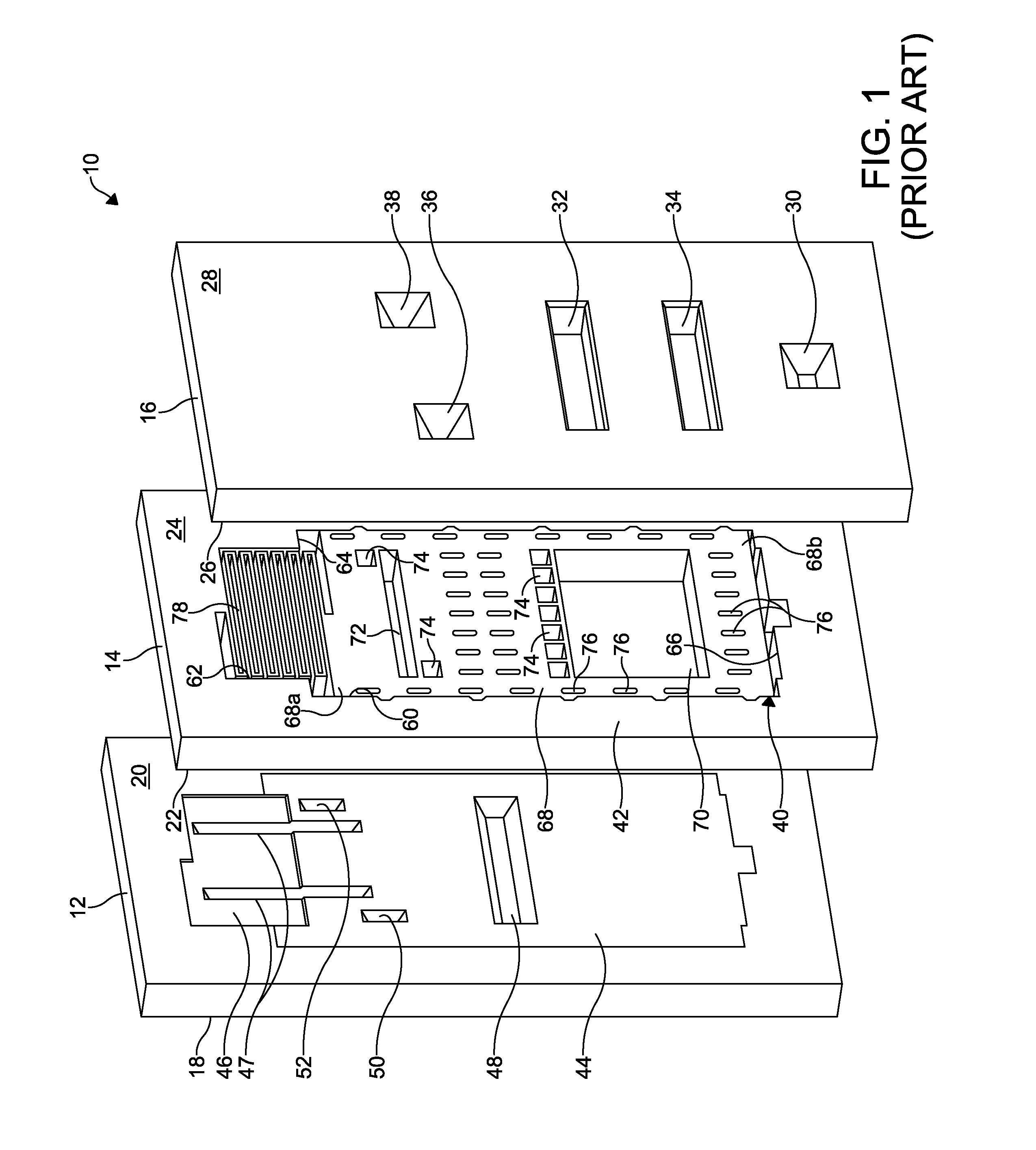
[0021]Referring now to the drawings, an embodiment of a known microvalve is indicated generally at 10 in FIGS. 1 through 3. The illustrated microvalve 10 is a pilot operated plate microvalve, similar to the embodiments of the microvalve disclosed in U.S. Pat. No. 8,393,344 to Hunnicutt, the disclosure of which in incorporated herein in its entirety.

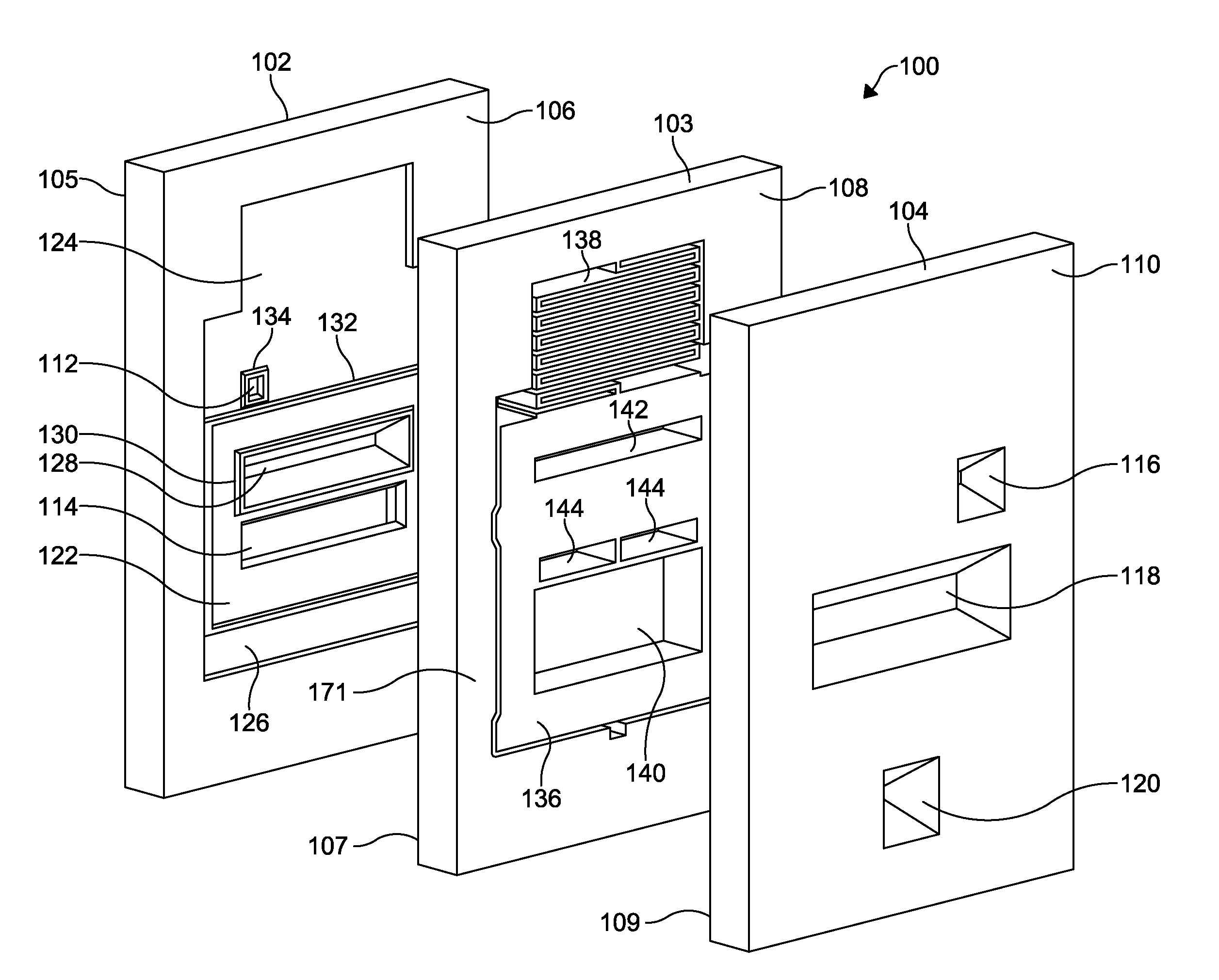
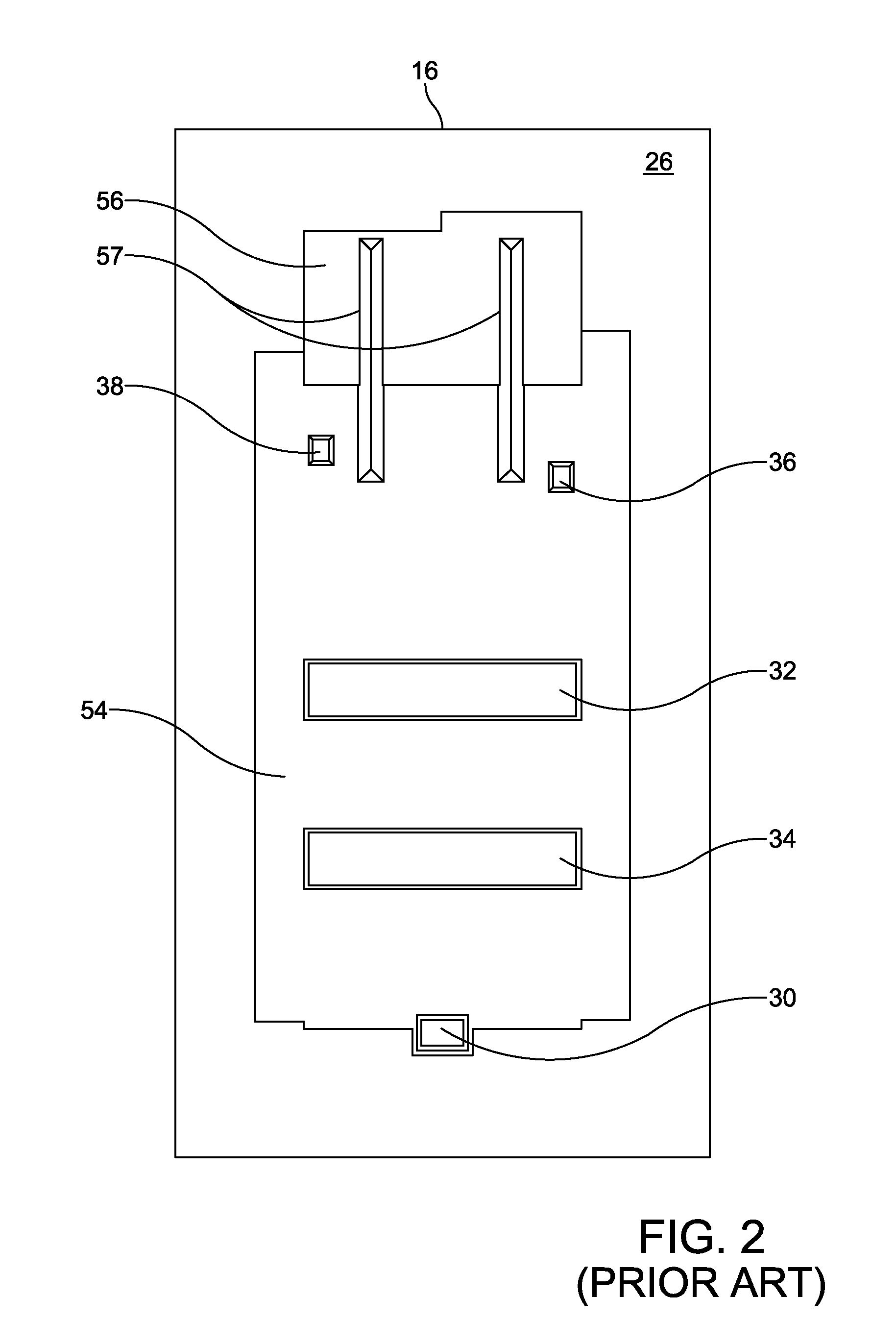
[0022]As shown in FIG. 1, the microvalve 10 includes a cover plate 12, an intermediate plate 14, and a base plate 16. The cover plate 12 has an outer surface 18 and an inner surface 20. The intermediate plate 14 has a first surface 22 and a second surface 24 and defines a movable portion 40 and a non-movable portion 42. The base plate 16 has an inner surface 26 and an outer surface 28. The base plate 16 also has a command port 30, an input port 32, an output port 34, a reference inlet port 36, and a reference outlet port 38 formed therethrough.

[0023]When the microvalve 10 is assembled as shown in FIG. 3, the inner surface 20 of the cover ...


PUM


Abstract

A microvalve includes a first plate having a surface, a recessed region provided within the surface, a fluid port provided within the recessed region, and a sealing structure extending about the fluid port. A second plate defines a non-movable portion and a movable portion, a surface of the non-movable portion abutting the surface of the first plate, the non-movable portion having first and second openings formed therethrough. The movable portion is formed within the first opening and has an axis, the movable portion defining a displaceable member connected to the non-movable portion by a convoluted spring formed in a second opening. The displaceable member is slidingly and axially movable within the first opening between a closed position, wherein the displaceable member cooperates with the sealing structure to prevent fluid communication through the fluid port, and an opened position, wherein the displaceable member does not cooperate with at least a portion of the sealing structure to prevent fluid communication through the fluid port.

Description

CROSS REFERENCE TO RELATED APPLICATIONS[0001]This application claims the benefit of U.S. Provisional Application No. 62 / 037,321 filed Aug. 14, 2014, the disclosure of which is incorporated herein by reference.BACKGROUND OF THE INVENTION[0002]This invention relates in general to microvalves for controlling the flow of fluid through a fluid circuit. In particular, this invention relates to an improved structure for a plate microvalve that resists interference with the free movement of a displaceable member of the plate microvalve that might otherwise result from the presence of particulate contaminants contained in the fluid flowing therethrough.[0003]Generally speaking, a micro-electro-mechanical system is a system that not only includes both electrical and mechanical components, but is additionally physically small, typically including features having sizes in the range of ten micrometers or smaller. The term “micro-machining” is commonly understood to relate to the production of th...

Claims


Application Information

Patent Timeline
Patent Type & Authority Applications(United States)
IPC IPC(8): F16K99/00
CPCF16K99/0011
Inventor FULLER, EDWARD NELSONARUNASALAM, PARTHIBANYANG, CHENOJEDA, SR., JOE A.GURLEY, GENGXUN K.
Owner DUNAN MICROSTAQ
Why Eureka
Try Eureka