State monitoring or diagnostics system

a state monitoring or diagnostics system technology, applied in the field of state monitoring or diagnostics systems, can solve problems such as overloading protection devices, damage or destruction of electrical equipment, and inability to operate properly of protection devices, and achieve the effect of simple construction and economical

Active Publication Date: 2015-10-27
PHOENIX CONTACT GMBH & CO KG
View PDF9 Cites 1 Cited by
  • Summary
  • Abstract
  • Description
  • Claims
  • Application Information

AI Technical Summary

Benefits of technology

[0006]Therefore, the object of the present disclosure is to provide a state monitoring or diagnostics system, or a method for monitoring the state of devices or for diagnosing devices, that is simply constructed and economical.
[0008]A further object of the present disclosure is to provide a method for transmitting measured values that functions without its own electrical power supply and is simple and economical.
[0016]The use of RFID transponders is quite deliberately avoided, which has the advantage that the monitoring and transmitting apparatus has high electromagnetic compatibility and, moreover, is extremely resistant to interference in general, e.g. from the electromagnetic pulses (EMP, especially LEMP) that unavoidably occur at an overvoltage protection device. The information to be interrogated is thus “stored” exclusively in the resonant frequency (value or presence) of the resonator circuit. Moreover, not only is it cost-effective to use the present disclosure with relatively expensive electrical equipment, but it is also so economical that the present disclosure can even be used with very simple “low cost products,” such as with plug-in connectors, terminals, etc.
[0024]The overvoltage is indeed safely arrested by the overvoltage protection component, but now it is possible to determine, using the present disclosure, whether an overvoltage protection device has arrested an overvoltage and if so, which device, with the determination being made in a contactless manner from outside by means of the electromagnetic response oscillations of the resonant circuits. The device need not necessarily be faulty, but the present disclosure makes it possible to replace the overvoltage protection device for safety reasons when it has triggered.

Problems solved by technology

Overvoltages are potentially disruptive factors that can cause damage or destruction in electrical equipment.
Although overvoltage protection devices are designed to withstand high transient current loads, high-energy overvoltage interference can nevertheless overload the protection devices.
When an overvoltage pulse occurs, it is possible for the pulse to be properly arrested by the overvoltage protection device although the overvoltage protection device is itself damaged by the event.
Then, the overvoltage protection device may no longer function properly at the next occurrence of an overvoltage, and the electrical equipment may suffer damage that the overvoltage protection device is specifically intended to prevent.
In the event of a fault in the overvoltage protection device, the error detection unit is caused to short-circuit or interrupt the transponder antenna circuit or to change the resonant frequency of the transponder antenna circuit.
However, the use of RFID transponders, especially in overvoltage protection devices, entails the risk that the RFID transponders themselves can be destroyed by an electromagnetic pulse.
In this context, a problem with the method described in DE 10 2004 006 987 is that in some cases it may not be possible to identify whether the RFID transponder has been destroyed or whether the error detection unit has triggered.
It is possible, namely, that the RFID transponder has been destroyed but that the overvoltage protection device itself is still functional.
This can result in an unnecessary and costly replacement.
In addition, RFID transponders have low electromagnetic compatibility (EMC), which is especially problematic for the stated applications.
Apart from this, the use of RFID transponders is complicated and costly, which limits their use to relatively complex equipment.

Method used


Image

  • State monitoring or diagnostics system
  • State monitoring or diagnostics system
  • State monitoring or diagnostics system

Examples


Embodiment Construction

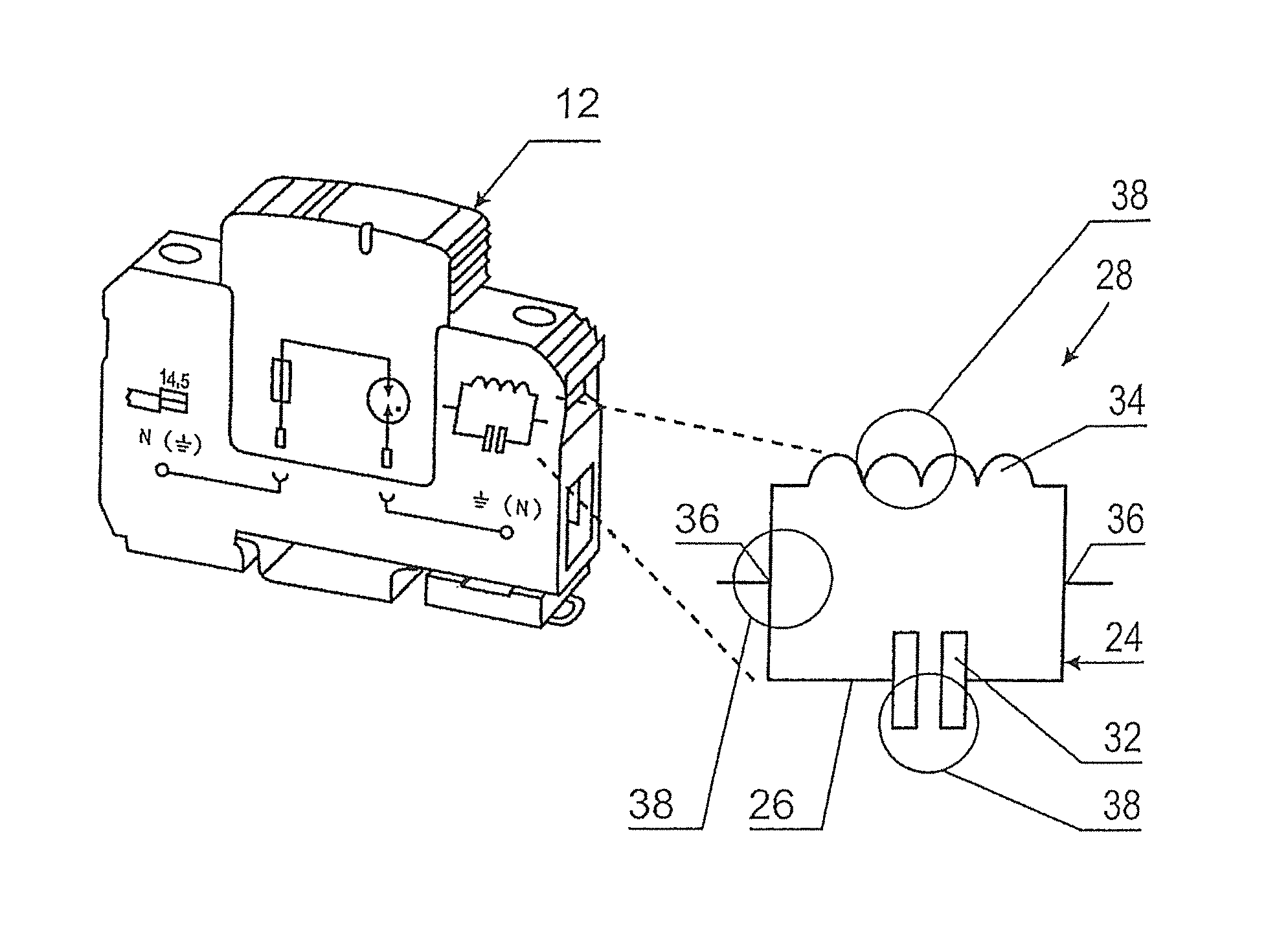
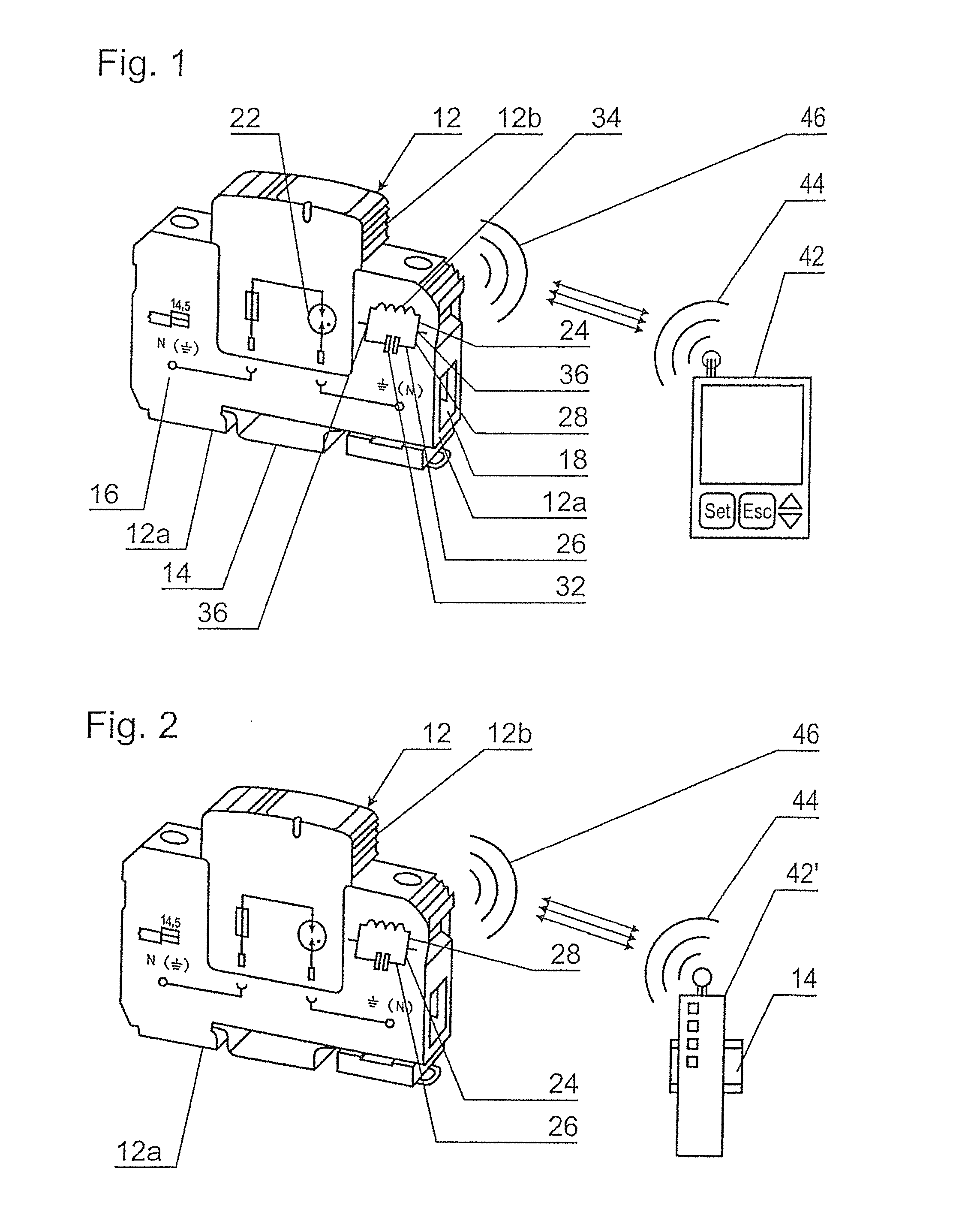
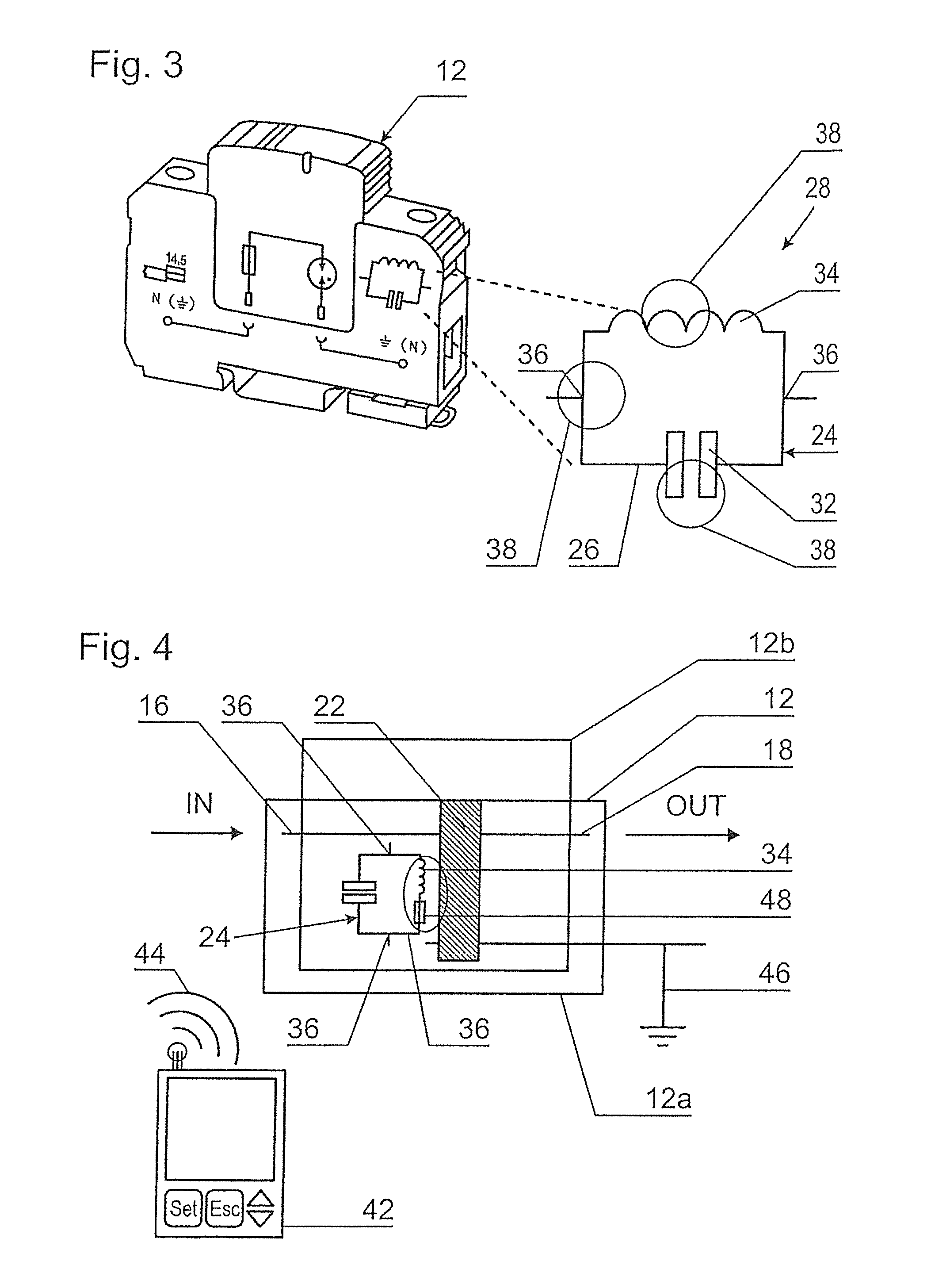
[0037]With reference to FIG. 1, an overvoltage protection device or overvoltage protection module 12 is mounted on a top-hat rail 14, typically in an equipment cabinet (not shown). The overvoltage protection module 12 has an input 16 and an output 18, and is constructed in two parts from two submodules 12a and 12b, wherein the submodule 12a is mounted on the top-hat rail and contains the overvoltage protection component 22. The submodule 12b is plugged in to the submodule 12a so that the submodule 12b can be replaced if necessary without the need to replace the submodule 12a. The overvoltage protection module 12 shown by way of example is part of the applicant's TRABTECH line. In this example, the overvoltage protection component 22 is implemented as a gas discharge arrester with a gas discharge tube and is symbolized on the side of the submodule 12a.

[0038]According to the present disclosure, the overvoltage protection module 12 has a resonator circuit 24 as a monitoring and transm...


PUM


Abstract

The present disclosure concerns a state monitoring or diagnostics system, and also a method for monitoring the state of devices or for diagnosing devices, in particular for overvoltage protection devices, as well as a method for transmitting measured values. Each of the devices comprises a functional component to be monitored and a monitoring and transmitting apparatus, wherein the monitoring and transmitting apparatus consists solely of a resonator circuit made of passive electrical components with no microchip, in particular with no RFID transponder. The information to be interrogated resides in the resonant frequency of the resonator circuit.

Description

TECHNICAL FIELD[0001]The present disclosure concerns a state monitoring or diagnostics system and also a method for monitoring the state of devices or for diagnosing devices, for example for overvoltage protection devices, as well as a system and method for transmitting measured values.BACKGROUND[0002]Overvoltages are potentially disruptive factors that can cause damage or destruction in electrical equipment. For this reason, overvoltage protection devices are employed in many areas of electrical engineering, such as in electric power engineering, measurement, control, and regulation technology, information technology, and for transmitting and receiving facilities. Examples of this can be found at www.phoenixcontact.de / ueberspannungsschutz, for example.[0003]Although overvoltage protection devices are designed to withstand high transient current loads, high-energy overvoltage interference can nevertheless overload the protection devices. When an overvoltage pulse occurs, it is possi...

Claims


Application Information

Patent Timeline
Patent Type & Authority Patents(United States)
IPC IPC(8): H01H31/02G01R1/36H01T1/12G06K19/07G01R23/02
CPCG01R1/36G01R23/02G06K19/0717H01T1/12
Inventor BENT, ROLANDKALHOFF, JOHANNES
Owner PHOENIX CONTACT GMBH & CO KG
Why Eureka
Try Eureka