Magnetic encoder

Inactive Publication Date: 2011-12-15
CONTINENTAL TEVES AG & CO OHG
View PDF7 Cites 1 Cited by
  • Summary
  • Abstract
  • Description
  • Claims
  • Application Information

AI Technical Summary

Benefits of technology

[0015]As a result, there is already a substantially linear relationship between field angle or detectable magnetic field and measurement variable or relative position between the encoder and a magnetic field sensor element at the surface of the encoder. For this reason, the reading distance or air gap between the encoder and magnetic field sensor element can be kept relatively low, that is to say considerably smaller than half the pole length, when the magnetic encoder according to aspects of the invention is used in a sensor arrangement for field angle / field direction detection. In addition, only a relatively low material thickness of the encoder is therefore required, this permitting a reduction in cost, and the resistance to interference or the signal-to-noise ratio of the sensor arrangement is likewise improved by the short air gap length which can now be applied.

Problems solved by technology

Any deviation from this causes an error or at least expenditure on correction in the measurement system.
One disadvantage of this block-like magnetization is the high cross sensitivity in terms of the reading distance or the normal distance of the magnetic field sensor element from the encoder track or the encoder surface.
However, these requirements conflict with the following restrictions: each encoder generates the maximum field strength directly at its surface.
Encoders with a high material thickness, for example with a thickness of at least half a pole length, can be completely magnetized only with relative difficulty.
The greater the requirements made of the sensor arrangement, the greater the conflict in terms of objective with regard to the reading distance: a greater distance means an increase in linearity but a loss in field strength and therefore a worsening of the signal-to-noise ratio or signal-to-interference ratio at the magnetic field sensor element.

Method used


Image

  • Magnetic encoder
  • Magnetic encoder
  • Magnetic encoder

Examples


Embodiment Construction

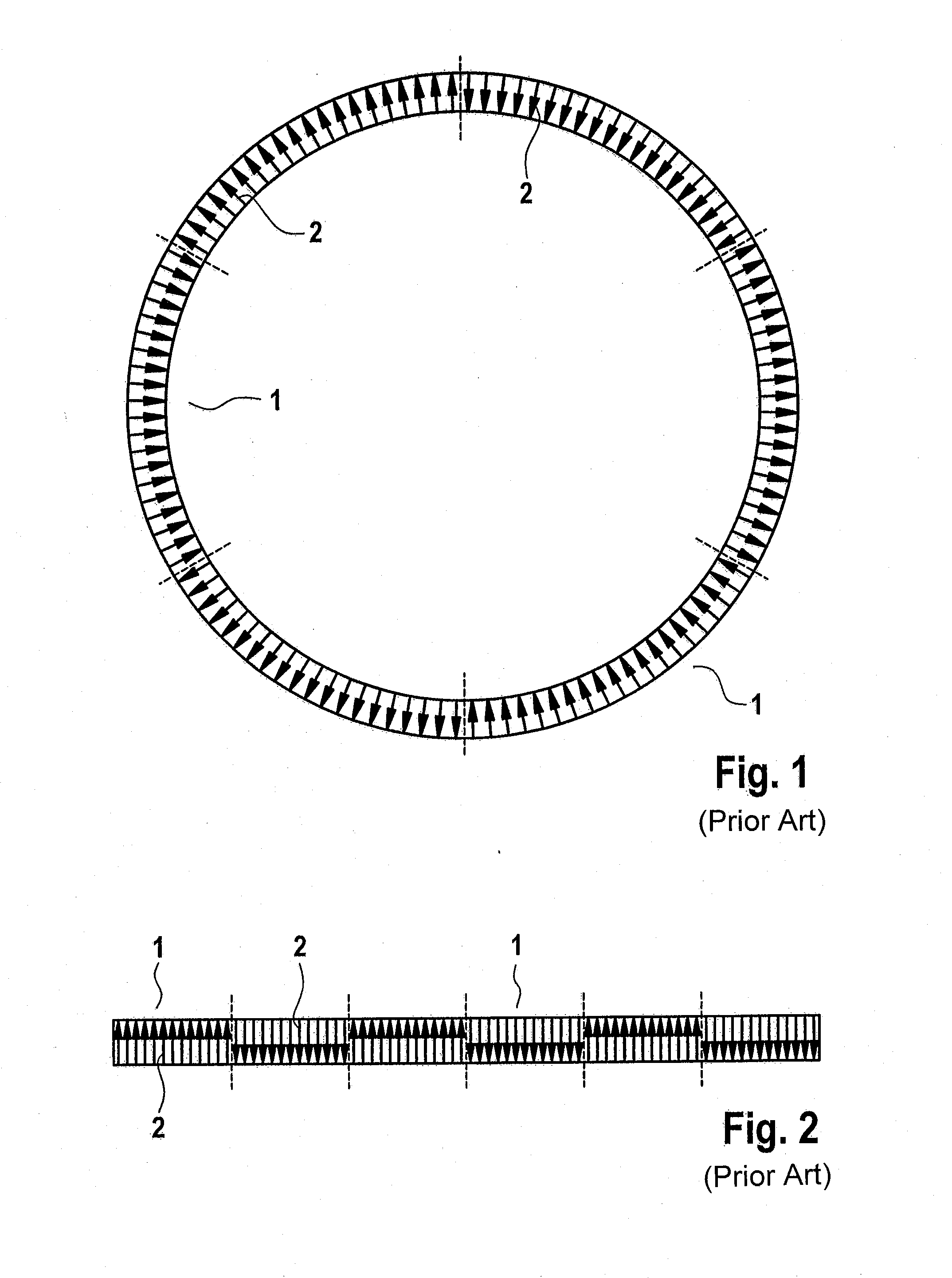
[0042]FIG. 1 shows an annular encoder with six poles and FIG. 2 shows a linear or straight encoder with six poles, both encoders being formed in a conventional manner. The magnetization directions 2 of individual subregions of the poles 1 are represented by arrows. The poles 1 are magnetized in a homogeneous or block-like manner. The encoders therefore have an alternating north / south magnetization. The arrangement of the poles in series forms, for example, the encoder track.

[0043]A magnetic field sensor element (not illustrated) detects, in the close range or when the air gap is relatively small, the block-like or box-profile-like magnetizations of the poles over their homogeneous magnetic field. Only when there is a relatively large air gap can the magnetic field sensor arrangement carry out an angular measurement in which the detected angle of the magnetic field rotates with any kind of uniformity along the encoder track, since, when there is a relatively large distance from the e...


PUM

PropertyMeasurementUnit
Angleaaaaaaaaaa
Angleaaaaaaaaaa
Angleaaaaaaaaaa

Abstract

A magnetic encoder having at least one encoder track including one or more pole pairs, wherein the magnetization directions of subregions within at least one of the poles are embodied so as to change substantially continuously and / or monotonically along the encoder track.

Description

CROSS REFERENCE TO RELATED APPLICATIONS[0001]This application is the U.S. National Phase Application of PCT International Application No. PCT / EP2009 / 066137, filed Dec. 1, 2009, which claims priority to German Patent Application No. 10 2008 059 774.0, filed Dec. 1, 2008, the contents of such applications being incorporated by reference herein.FIELD OF THE INVENTION[0002]The invention relates to a magnetic encoder, a method for producing a magnetic encoder and the use of the magnetic encoder in motor vehicle sensor arrangements.BACKGROUND OF THE INVENTION[0003]Magnetic encoders which are used in sensor arrangements for directly or indirectly measuring variables, for example rotational angle, length or speed, are known. These magnetic encoders are normally permanently magnetic or hard-magnetic and have an encoder track with a plurality of pole pairs, with the magnetic field of these poles being detected by one or more magnetic field sensor elements.[0004]The information which the encod...

Claims


Application Information

Patent Timeline
IPC IPC(8): G01B7/30G11B5/127
CPCB62D15/0215G01D5/145G01D2205/80Y10T29/49021G01B7/30G01D5/14
Inventor ACKER, HEINRICH
Owner CONTINENTAL TEVES AG & CO OHG
Why Eureka
Try Eureka