Methods and systems for operating an engine in a hybrid vehicle driveline

a hybrid vehicle and driveline technology, applied in the direction of machines/engines, process and machine control, instruments, etc., can solve the problems of engine efficiency, engine efficiency decline, and change in fuel consumption, so as to improve hybrid driveline efficiency, increase driveline efficiency, and improve engine efficiency

Active Publication Date: 2016-03-03
FORD GLOBAL TECH LLC
View PDF7 Cites 1 Cited by
  • Summary
  • Abstract
  • Description
  • Claims
  • Application Information

AI Technical Summary

Benefits of technology

[0004]By applying different filters to desired engine power, it may be possible to retain engine operation within a range where engine efficiency is greater for a longer period of time, thereby improving hybrid driveline efficiency. In particular, if desired engine power is within a defined efficient engine operating range, desired engine power may be more heavily filtered so that if desired engine power exits the defined efficient engine operating range, filtered engine power may remain in the defined efficient engine operating range. The engine may be operated at the filtered engine power to increase driveline efficiency. A motor / generator may provide a difference in power between the desired engine power and the filtered engine power so that driver demand torque may be provided. On the other hand, if desired engine power is outside of the defined efficient engine operating range, the filtered engine power may be less heavily filtered so that if desired engine power enters the defined efficient engine operating range, filtered engine power may enter the defined efficient engine operating range sooner than if desired engine power were filtered as if desired engine power was in the defined efficient engine operating range.
[0005]The present description may provide several advantages. In particular, the approach may improve vehicle efficiency. Additionally, the approach may provide fewer transitions between engine operating conditions. Further, the approach may provide lower vehicle emissions.

Problems solved by technology

The changes in fuel consumption may be related to engine pumping losses, engine friction, accessory losses, knock limits, and other conditions.
Consequently, it may be desirable to operate the engine at one condition to conserve fuel; however, the hybrid driveline may not be able to provide driver demand torque over a desired driveline operating range when engine torque is confined to efficient engine operating conditions.
Therefore, the hybrid driveline may be operated at conditions where the engine is less efficient than is desired to meet driver demand over a wide range of vehicle speeds.

Method used


Image

  • Methods and systems for operating an engine in a hybrid vehicle driveline
  • Methods and systems for operating an engine in a hybrid vehicle driveline
  • Methods and systems for operating an engine in a hybrid vehicle driveline

Examples


Embodiment Construction

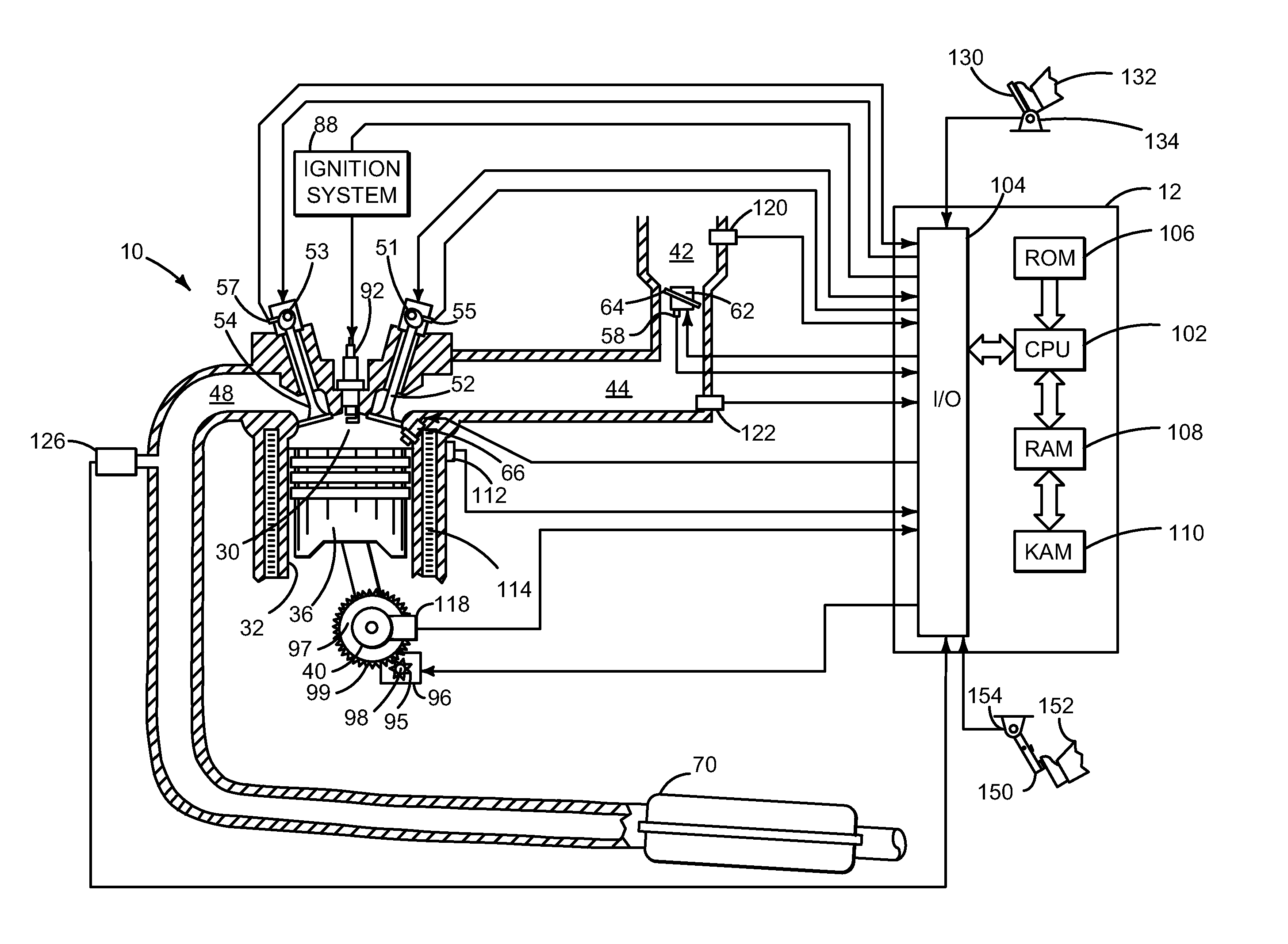
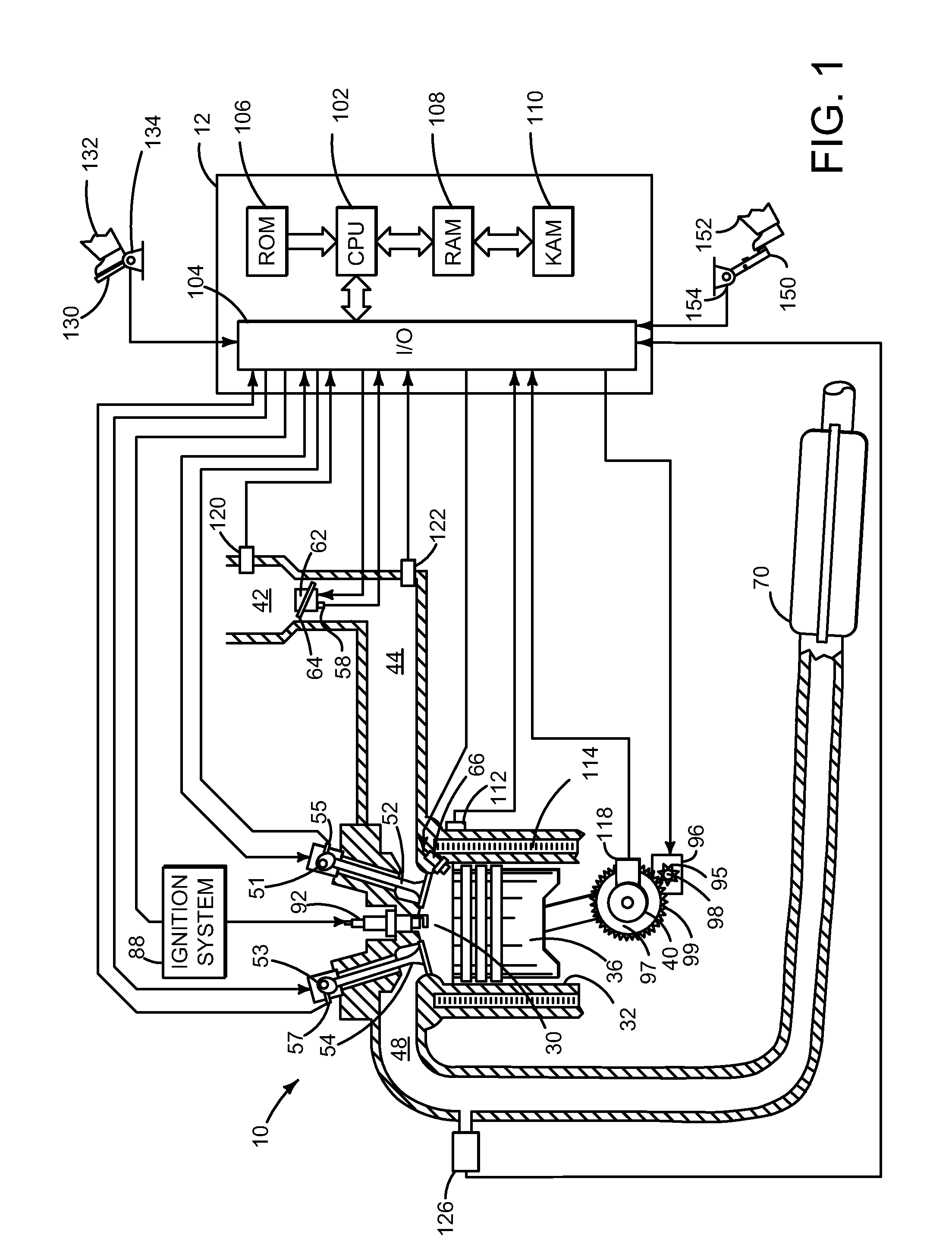
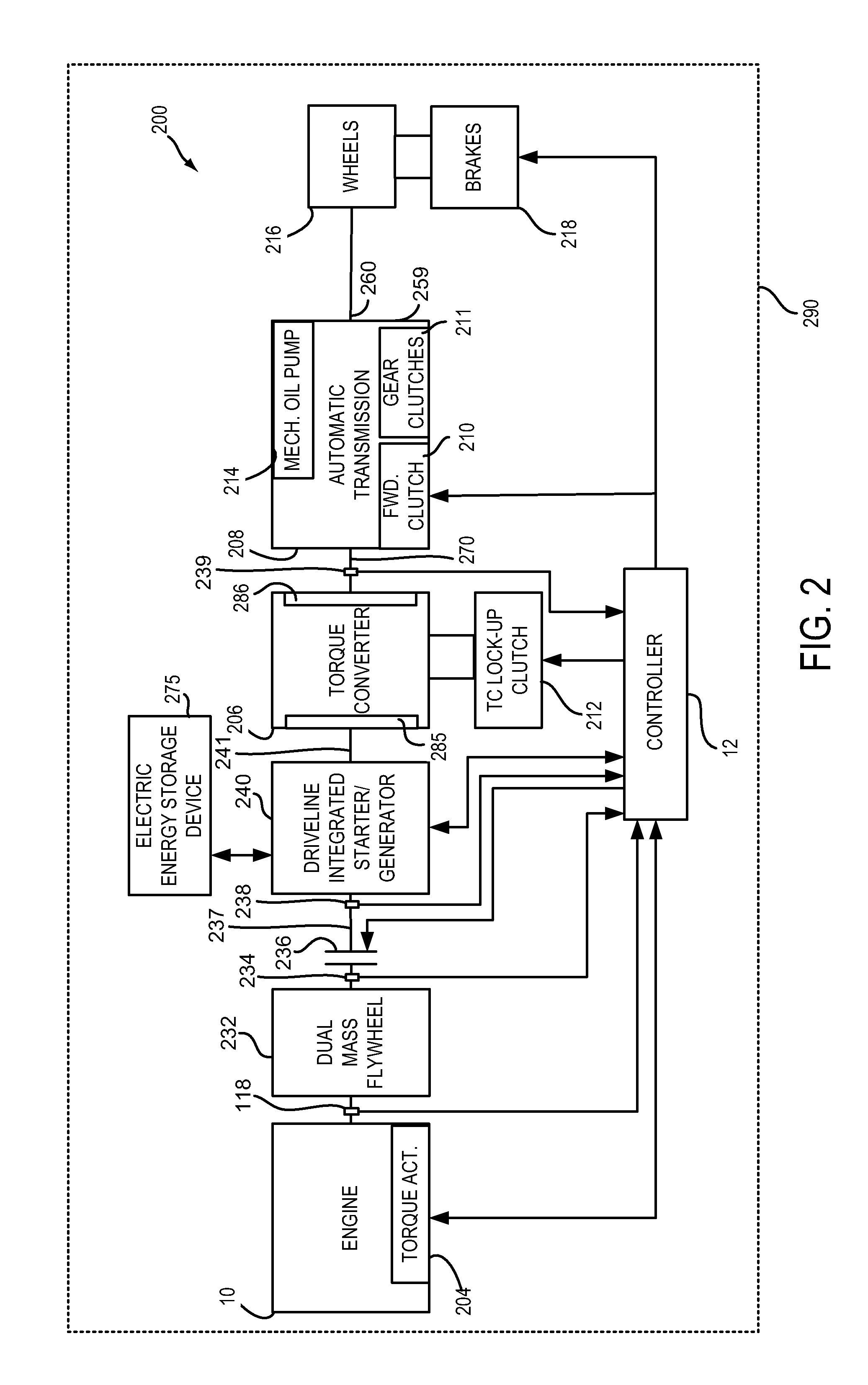
[0014]The present description is related to improving engine efficiency over a hybrid vehicle's operating range. The hybrid vehicle driveline may include an engine as shown in FIG. 1 that may be selectively coupled to a motor / generator to provide input to a transmission as is shown in FIG. 2. Alternatively, the engine of FIG. 1 may be included in a power split hybrid driveline with a motor and a generator as is shown in FIG. 3. Example efficient engine operating ranges within an engine operating domain are shown in FIG. 4. Finally, FIG. 5 shows a method for increasing an amount of time an engine operates at efficient operating conditions.

[0015]Referring to FIG. 1, internal combustion engine 10, comprising a plurality of cylinders, one cylinder of which is shown in FIG. 1, is controlled by electronic engine controller 12. Engine 10 includes combustion chamber 30 and cylinder walls 32 with piston 36 positioned therein and connected to crankshaft 40. Flywheel 97 and ring gear 99 are co...


PUM


Abstract

Systems and methods for increasing hybrid driveline efficiency are disclosed. In one example, an efficient engine operating region is defined within an engine operating domain based on an engine's brake specific fuel consumption. The systems and methods may increase an amount of time a hybrid driveline operates at more efficient operating conditions.

Description

FIELD[0001]The present description relates to a system and method for determining desired operation conditions for a hybrid driveline. The methods and systems may be useful for a variety of hybrid drivelines including series and parallel configurations.BACKGROUND AND SUMMARY[0002]A hybrid vehicle may include an engine and a motor for propelling the hybrid vehicle. The engine may operate at various speeds and loads to provide a desired driver demand torque while the hybrid vehicle is operating. The engine's brake specific fuel consumption may vary significantly between different operating conditions. The changes in fuel consumption may be related to engine pumping losses, engine friction, accessory losses, knock limits, and other conditions. Consequently, it may be desirable to operate the engine at one condition to conserve fuel; however, the hybrid driveline may not be able to provide driver demand torque over a desired driveline operating range when engine torque is confined to ef...

Claims


Application Information

Patent Timeline
Patent Type & Authority Applications(United States)
IPC IPC(8): F02D29/02B60W10/06B60W10/08B60W20/00
CPCF02D29/02B60W10/06B60W10/08Y10S903/902B60W2510/0666B60W2710/0677B60W20/10B60W2710/0666B60W2710/083B60W2520/28B60W2540/10B60W2050/0054Y02T10/40Y02T10/62
Inventor MARTIN, DOUGLAS, RAYMONDMILLER, KENNETH, JAMESSHEN, STEPHEN, LI-CHUN
Owner FORD GLOBAL TECH LLC
Why Eureka
Try Eureka