Developer container and image forming apparatus including the same

a technology of image forming apparatus and developer container, which is applied in the field of developer container, can solve the problems of difficulty in using up all the toner in the container, and achieve the effect of reducing the amount of developer

Active Publication Date: 2016-03-03
KYOCERA DOCUMENT SOLUTIONS INC
View PDF1 Cites 1 Cited by
  • Summary
  • Abstract
  • Description
  • Claims
  • Application Information

AI Technical Summary

Benefits of technology

[0008]The present invention provides a developer container capable of reducing the amount of developer remaining in a container body at the end of use of the developer container and constantly discharging developer, and an image forming apparatus including the developer container.

Problems solved by technology

In the toner container disclosed in Japanese Unexamined Patent Publication No. 2003-280344, toner is liable to remain in the region not affected by the rotational force of the conveying member, which makes it difficult to use up all the toner in the container.
This has been a problem.

Method used


Image

  • Developer container and image forming apparatus including the same
  • Developer container and image forming apparatus including the same
  • Developer container and image forming apparatus including the same

Examples


first embodiment

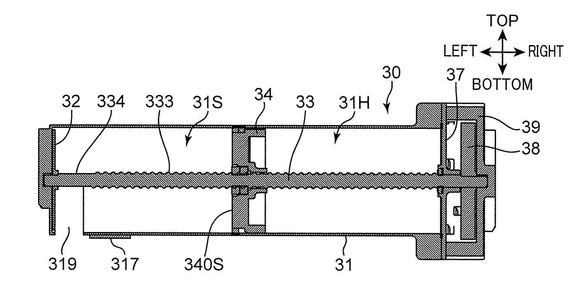
[0068]Now there will be described a toner container 30 (developer container) according to the present invention with reference to FIGS. 6 to 11. FIGS. 6 and 7 are perspective views of the toner container 30 according to the present embodiment. FIG. 8A is a plan view of the toner container 30, FIG. 8B is a front view of the toner container 30, and FIG. 8C is a side view of the toner container 30. FIG. 9 is an exploded perspective view of the toner container 30. FIGS. 10A and 10B are perspective views of a movable wall 34 of the toner container 30. FIG. 11 is a sectional view of the toner container 30.

[0069]The toner container 30 is substantially in the form of a cylinder. The toner container 30 contains replenishment toner (developer). With reference to FIGS. 9 and 11, the toner container 30 includes a container body 31 (container body), a stirring disc 32, a shaft 33 (shaft), the movable wall 34, a washer 35 (FIG. 9), a sponge seal 36, a lid 37, a rotary gear 38 (drive transmitter),...

second embodiment

[0111]With reference to FIG. 13A, the toner container 30P includes a container body 31P, a stirring disc 32P (stirring member, first rotary member), a shaft 33P, a movable wall 34P, and a lid 37P. Further, in the second embodiment, the stirring disc 32P includes a disc portion 32P1 secured to the shaft 33P, and the first coil spring 60 (projecting portion, coil spring) projecting from the disc portion 32P1 toward the lid 37P of the container body 31P (toward a conveying surface of the movable wall 34P).

[0112]The first coil spring 60 can expand and contract as shown in FIG. 14A. In the second embodiment, the first coil spring 60 has an outer diameter slightly smaller than an inner diameter of the container body 31P. The first coil spring 60 includes a first spring base end 601 and a first spring leading end 602. The first spring base end 601 is secured to the disc portion 32P1. A leading portion of the coil spring 60 including the first spring leading end 602 extends toward the lid 3...

third embodiment

[0118]With reference to FIG. 15A, the toner container 30Q includes a container body 31Q, a stirring disc 32Q (stirring member, first rotary member), a shaft 33Q, the movable wall 34Q, and a lid 37Q. Further, in the third embodiment, the stirring disc 32Q includes a disc portion 32Q1 secured to the shaft 33Q, and the stirring films 62 (projecting portion, film member) projecting from the disc portion 32Q1 toward the lid 37Q of the container body 31Q (toward the conveying surface of the movable wall 34Q).

[0119]The stirring films 62 include a pair of rectangular film members disposed across the shaft 33Q. The stirring films 62 each include a film base end 621 and a film leading end portion 622. The film base ends 621 are secured to the disc portion 32Q1. The film leading end portions 622 of the stirring films 62 extend toward the lid 37Q in a storage space 31 SQ.

[0120]Also in the third embodiment, the stirring films 62 rotate with the shaft 33Q in the storage space 31SQ, and this toner...


PUM


Abstract

A developer container (30) includes a container body (31), a movable wall (34), and a stirring member (32). The container body (31) includes an inner surface (31K) defining a cylindrical internal space (31H) extending in a longitudinal direction, and a developer discharge port (319). The developer discharge port (319) is formed in a lower part of the inner surface (31K). The movable wall (34) includes an outer surface (34K) disposed slidably in close contact with the inner surface (31K) of the container body (31), and a conveying surface (340S). The conveying surface (340S) defines a storage space (31S) for developer. The movable wall (34) moves while conveying the developer in the storage space (31 S) to the developer discharge port (319). The stirring member (32) stirs developer in the storage space (31 S).

Description

TECHNICAL FIELD[0001]The present invention relates to a developer container for containing developer and an image forming apparatus including the developer container.BACKGROUND ART[0002]Conventionally, toner containers such as one disclosed in Japanese Unexamined Patent Publication No. 2003-280344 are known as developer containers for containing developer. The toner container includes a toner discharge port and a rotary stirring member. Toner is discharged through the toner discharge port by rotation of the stirring member.[0003]Japanese Unexamined Patent Publication No. 2009-265395 discloses a waste toner container for containing developer. The waste toner container includes a cylindrical container body having an outer circumferential portion formed with a helical groove. Collected toner is conveyed to one end of the container body along the helical groove by rotation of the container body.[0004]In the toner container disclosed in Japanese Unexamined Patent Publication No. 2003-280...

Claims


Application Information

Patent Timeline
Patent Type & Authority Applications(United States)
IPC IPC(8): G03G15/08
CPCG03G15/0889G03G15/08G03G15/0872G03G15/0874G03G2215/085
Inventor KONISHI, HIROHITOETO, DAISUKE
Owner KYOCERA DOCUMENT SOLUTIONS INC
Why Eureka
Try Eureka