
HUD Object Design and Method

a head-up display and display environment technology, applied in the field of head-up display (hud) augmented reality (ar) display environment, can solve the problems of limited ability to display large-scaled 3-d models, users experiencing rendering latencies, and software not presenting objects in a first pla

Active Publication Date: 2016-03-10
SMITH CHARLES ANTHONY
View PDF5 Cites 29 Cited by
  • Summary
  • Abstract
  • Description
  • Claims
  • Application Information

AI Technical Summary

Benefits of technology

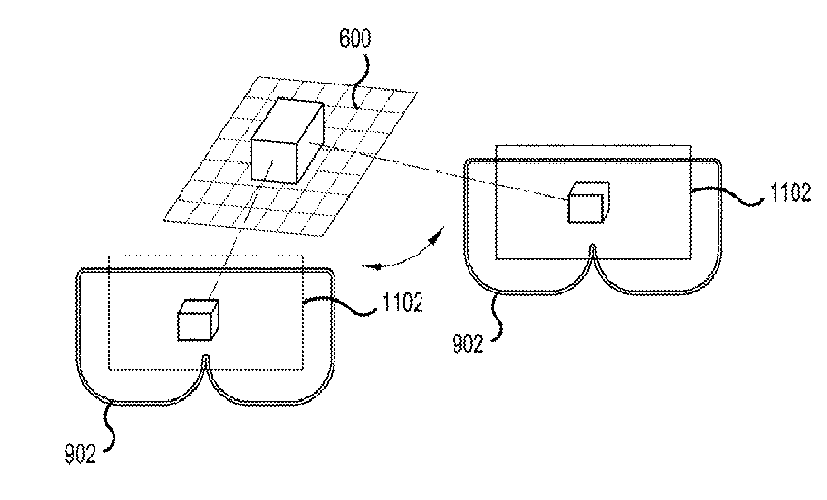
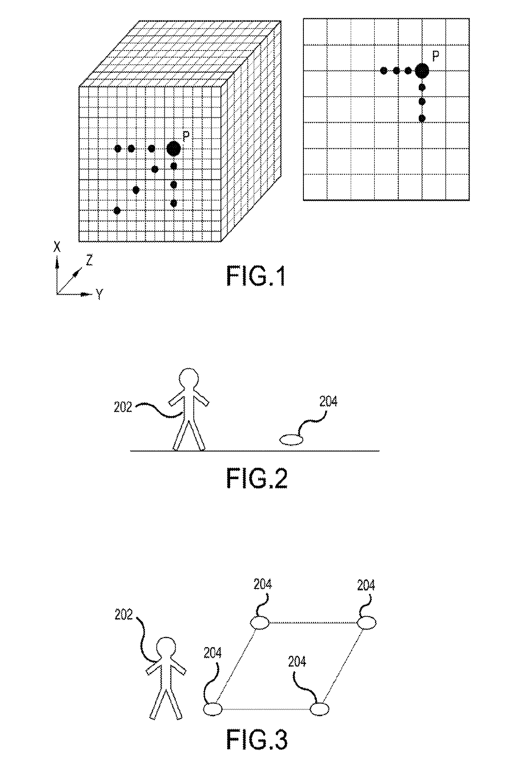
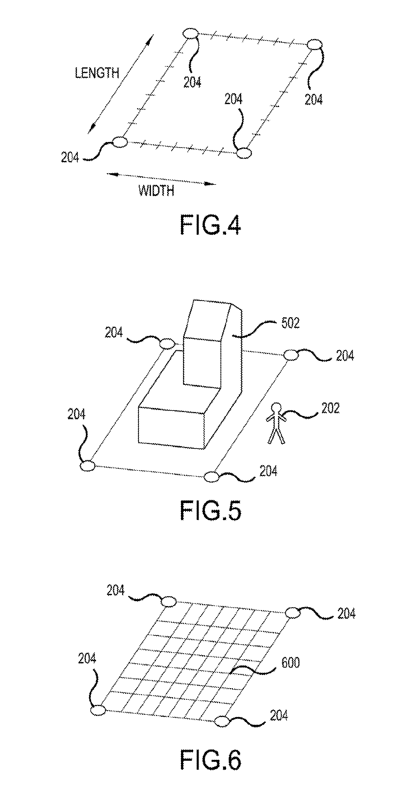
The present invention provides a user-friendly system for creating high-quality 3-D models and adding properties to them in a first person Augmented Reality (AR) view. It uses a heads-up display (HUD) and location sensors to create a realistic and immersive user experience. The invention features a rectangular grid and a motion sensor on the HUD to calculate the user's view of the rendered 3-D objects based on the movement of the HUD. The invention also allows for the creation of large-scaled environments and synchronization of multiple location sensors. The technical effects of the invention include improved user experience, better design and modeling of 3-D objects, and more realistic and immersive augmented reality environments.

Problems solved by technology

However, the software does not present the objects in a first person Augmented Reality (AR) view.
Also, this method limits the ability to display large scaled 3-D models.
Using Cameras instead of sensors can potentially cause users to experience rendering latencies, and range of view point limitations.
Further, in some instances, unique properties of the objects make it difficult to simulate physical or visual characteristics.

Method used


Image

  • HUD Object Design and Method
  • HUD Object Design and Method
  • HUD Object Design and Method

Examples


Embodiment Construction

[0054]Aspects of the present invention are directed to systems, methods and computer program products for enabling a first person augmented reality view, design and development of 3-dimensional objects. In one aspect of an embodiment of the present invention, computer program product for causing a computer to enable a first person augmented reality view of 3-dimensional objects is disclosed. The computer program product, as envisioned in this aspect, may include a computer usable medium having control logic stored on it for causing a computer to enable a first person augmented reality view of 3-dimensional objects. The control logic may include computer readable program code for a variety of operations including: initializing communication between a display device and one or more sensors, receiving sensor data from the one or more sensors, generating an augmented reality environment using data from the one or more sensors, incorporating a 3-dimensional target object within the augme...


PUM


Abstract

The invention features a rectangular 3-D modeling grid called a display environment that may be mapped to one or more sensor(s) to provide a heads up display device the ability to generate and view an Augmented Reality first; person view of custom 3-D objects. Location sensors create the positioning and perimeter of the display environment. The Display Environment may Sbe navigated by the combination of the display device's physical movement sensed by motion sensors and the display device's physical location based on its proximity to synchronized location sensors. Sensors on the display device recognize when the device is moving with respect to the Display Environment to initiate re-rendering of its 3-D model being displayed. Movement of the display device enable first person 3-D model illustrative and perspective views which may also be used to design 3-D models with customizable scale, orientation, positioning physics, and artificial intelligence.

Description

CROSS-REFERENCE TO RELATED APPLICATIONS[0001]This application claims priority to, the benefit of, and is related to, the Applicant's provisional application, U.S. Provisional Patent Application No. 61 / 828,745 titled “HUD Object Design and Method,” filed May 30, 2013.FIELD OF THE INVENTION[0002]The present invention relates, in general, to a head-up display (HUD) Augmented Reality (AR) Display Environment which can design three dimensional objects, add properties to the objects and show views of the object based on the movement of a HUD device and / or its inter-relationship with location sensor(s).BACKGROUND OF THE INVENTION[0003]Three dimensional (3-D) rendering refers to wire frame 3-D models that have been plotted to X, Y and Z grid lines and then converted to a 2-D image with 3-D effects. Although 3-D rendered objects are commonly seen, 3-D modeling software is required to create and render them. However, the software does not present the objects in a first person Augmented Realit...

Claims


Application Information

Patent Timeline
IPC IPC(8): G06T19/00G02B27/01G02B30/00G06T19/20
CPCG06T19/006G06T19/20G02B27/017G02B27/22G06T2219/2016G02B2027/0187G02B2027/014G06T2219/024G02B2027/0138G02B2027/0134G02B2027/0178G02B30/00
Inventor SMITH, CHARLES, ANTHONY
Owner SMITH CHARLES ANTHONY
Learn More