Coupler connector and cable terminator with side contacts

a technology of side contacts and connectors, which is applied in the manufacture of contact members, coupling device connections, electrically conductive connections, etc., can solve the problems of inadvertent disassembly of the assembly, inefficient and cumbersome, and limited mechanical strength of such prior art assemblies

Active Publication Date: 2016-03-10
BELDEN CANADA ULC
View PDF3 Cites 11 Cited by
  • Summary
  • Abstract
  • Description
  • Claims
  • Application Information

AI Technical Summary

Problems solved by technology

One drawback of such prior art assemblies is that they typically require the individual conductors of the communications cable to be threaded or fished through a small opening prior to being pierced by an insulation displacement connector or the like to provide conductive contact.
As a result, such prior art assemblies require skill and / or time to assemble and therefore are inefficient and cumbersome.
Additionally, the mechanical strength of such prior art assemblies is limited thereby allowing the assembly to be inadvertently disassembled, for example through forceful tugging on the cable or the like.

Method used


Image

  • Coupler connector and cable terminator with side contacts
  • Coupler connector and cable terminator with side contacts
  • Coupler connector and cable terminator with side contacts

Examples


Embodiment Construction

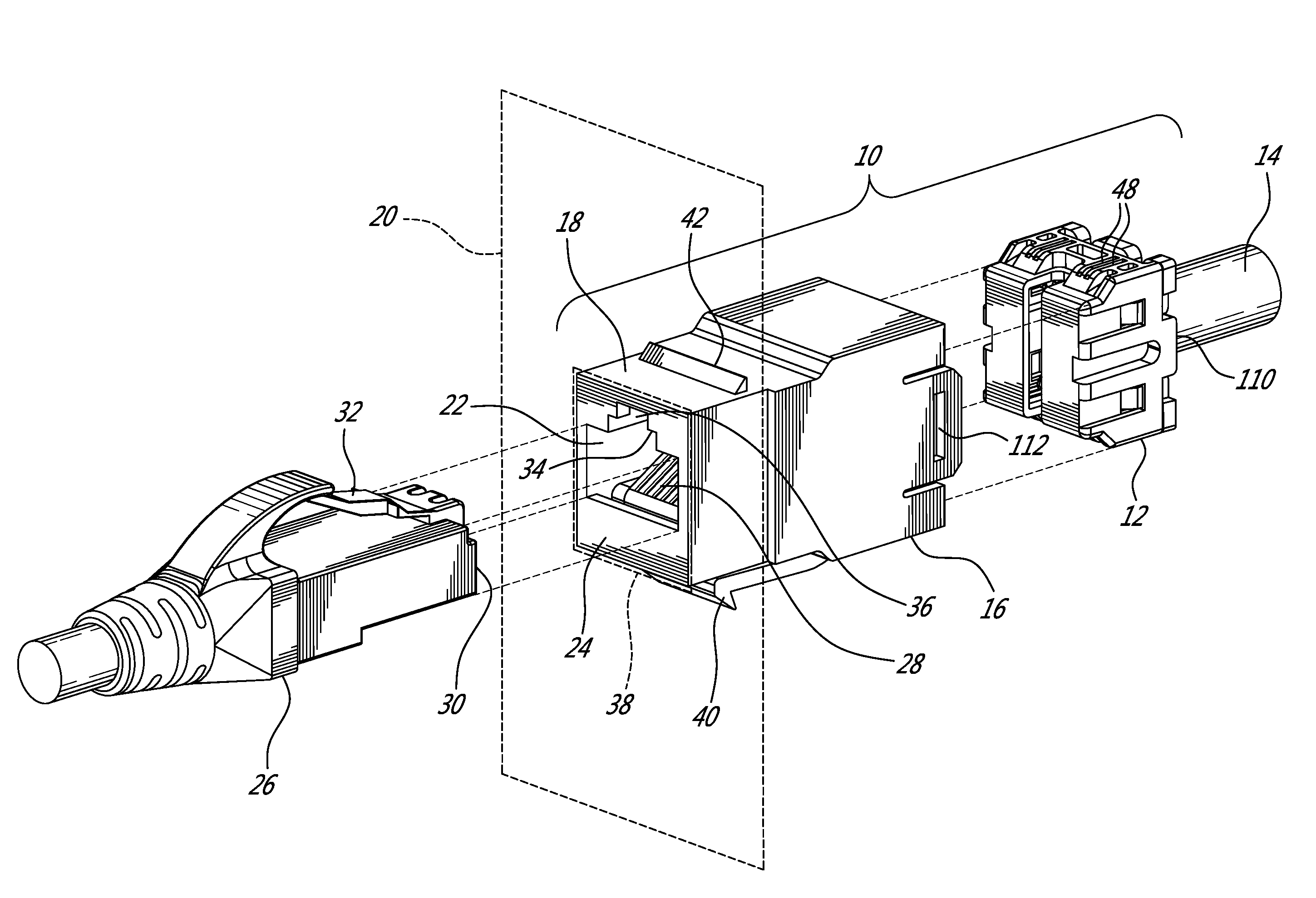
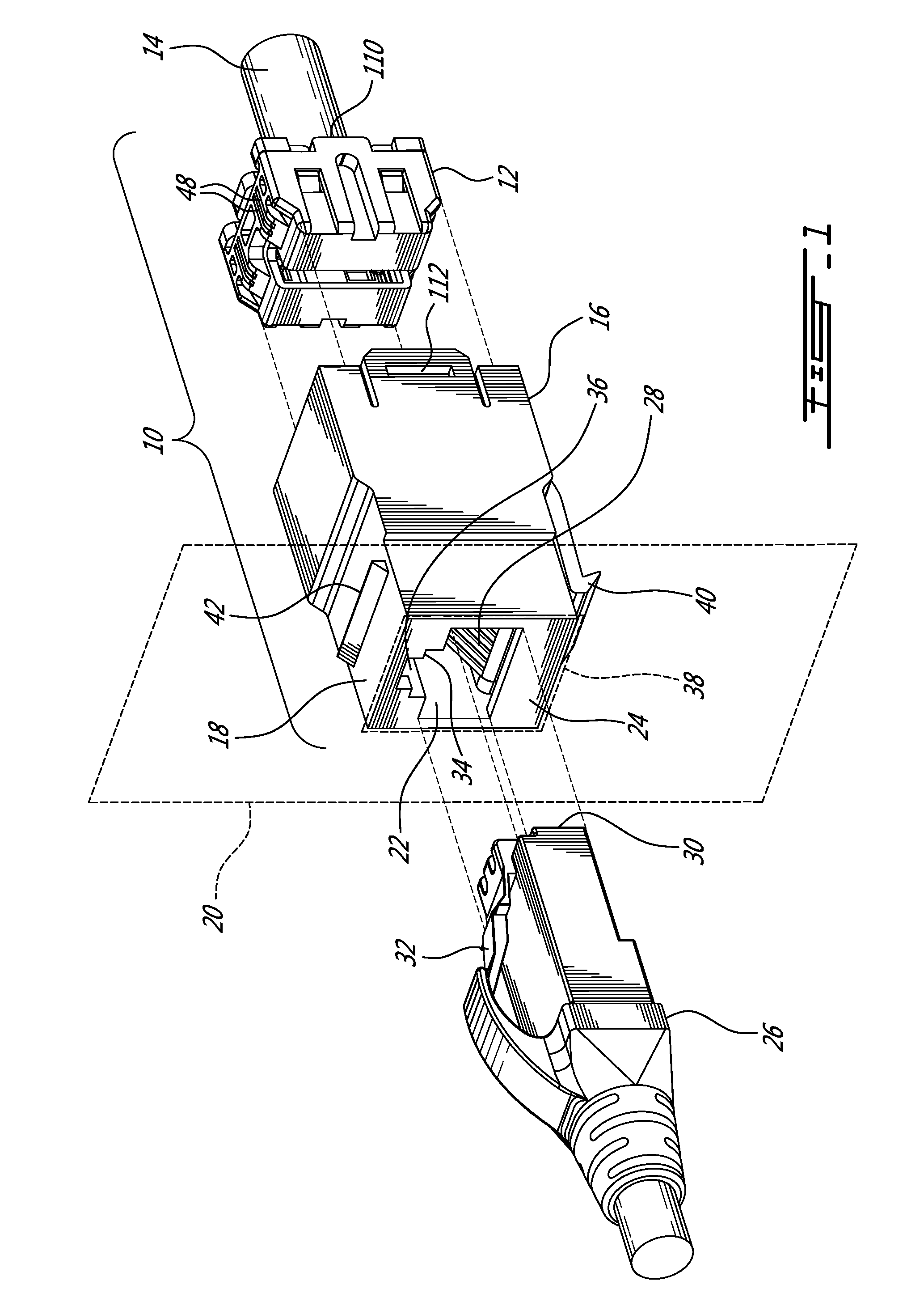
[0021]Referring now to FIG. 1, a coupler connector and cable terminator, generally referred to using the reference numeral 10, will now be described. The coupler connector and cable terminator comprises a cable terminator 12 which terminates a cable 14 comprising a plurality of pairs of conductors (not shown) which is inserted into a coupler connector 16. The coupler connector 16 illustratively comprises a keystone compatible type outer housing 18 rendering it suitable for insertion into a keystone compatible wall plate 20 or patch panel (not shown). The coupler comprises 16 further comprises a modular socket 22, illustratively an RJ-45 compatible socket, in a forward end 24 thereof for receiving a compatible plug 26 therein. A plurality of contact strips 28, or tines, are secured within the socket 22.

[0022]Still referring to FIG. 1, the plug 26 terminates a second cable 30 comprising a plurality of pairs of conductors (not shown). The plug 26 further comprises a plurality terminal ...


PUM


Abstract

An assembly comprising a cable terminator comprising a wire guide, a cube shaped securing cap comprising an open end for installation over the wire guide, and pairs of piercing contacts for piercing respective conductors of the cable. When assembled, an outer end of each of the piercing contacts is exposed on an outer surface of a respective securing cap sidewall. The assembly also comprises a coupler connector comprising one of a modular (for example RJ-45 compatible) socket or a modular (for example RJ-45 compatible) plug, a rearward surface comprising a cable terminator receiving socket, wherein pairs of contacts are exposed along at least one side wall of the socket, and further wherein each of a plurality of the tines in the modular socket or the terminal contacts of the plug is interconnected with a respective one of the contacts. When the cable terminator is inserted into the cable terminator receiving socket, each of the piercing contacts comes into contact with a respective one of the contacts, thereby interconnecting each of the tines (or each of the terminal contacts) with a respective one of the conductors. A back-to-back connector is also disclosed.

Description

CROSS REFERENCE TO RELATED APPLICATIONS[0001]This application claims benefit, under 35 U.S.C. §119(e) of U.S. provisional application Ser. No. 62 / 045,664, filed on Sep. 4, 2014 which is incorporated herein in its entirety by reference.FIELD OF THE INVENTION[0002]The present invention relates to a coupler connector and cable terminator with side contacts. In particular, the present invention relates to a connector for simplifying the installation of a modular receptacle or plug to the end of a cable comprising a plurality of twisted pairs of conductors.BACKGROUND TO THE INVENTION[0003]The prior art discloses a variety of assemblies for terminating communications cables in the field. One drawback of such prior art assemblies is that they typically require the individual conductors of the communications cable to be threaded or fished through a small opening prior to being pierced by an insulation displacement connector or the like to provide conductive contact. As a result, such prior ...

Claims


Application Information

Patent Timeline
Patent Type & Authority Applications(United States)
IPC IPC(8): H01R24/64H01R4/24H01R43/01
CPCH01R24/64H01R2107/00H01R43/01H01R4/2404H01R13/506H01R13/633H01R31/005H01R13/514H01R13/6272
Inventor FONTAINE, MARCPLAMONDON, JEAN-SEBASTIENSIEV, VIRAKDESROCHES, ALAINMILETTE, LUCBEAUREGARD, FRANCOIS
Owner BELDEN CANADA ULC
Why Eureka
Try Eureka