Flexible locked plate fixation

a flexible, fixed plate technology, applied in the field of fixed plate devices, can solve the problems of not always desirable absolute rigidity, and achieve the effect of reducing rigidity and rigidity

Inactive Publication Date: 2016-03-17
STRYKER EURO OPERATIONS HLDG LLC
View PDF0 Cites 17 Cited by
  • Summary
  • Abstract
  • Description
  • Claims
  • Application Information

AI Technical Summary

Benefits of technology

[0015]In another embodiment, the bone fixation device includes at least one oblong hole into which a bone screw can be inserted. The oblong shape of the hole allows movement of the screw along the major axis of the oblong hole, while tilting or movement in other directions is restricted by the minor axis of the oblong hole as well as other means. Examples of the other means contemplated herein include a nut, through which the screw is inserted, which at least partially contacts the underside of the bone fixation device to provide rigidity in the desired directions. Further means include a cap and screw assembly in which the screw can move with the bone in the direction of the main axis of the bone while still being restricted from movement in other directions by the cap.
[0016]Still further embodiments of the invention are provided to achieve axial dynamization of a bone. These include screw configurations in which a top portion of the screw is narrower than a bottom portion of the screw, due to either the core diameter or the thread diameter changing along the axis of the screw. This geometry allows for reduced rigidity on the near cortex side of the bone after the screw is inserted through an aperture in a bone fixation device and further through the bone. The reduced rigidity allows the screw and bone to move along the main axis of the bone while restricting movements in other directions. Similarly, an embodiment of the invention achieves a similar result using a screw with a constant core and thread diameter, but instead creating a relatively large drill hole in the near cortex and relatively small drill hole in the far cortex of the bone.

Problems solved by technology

However, absolute rigidity is not always desirable and it can be advantageous when an implantable bone plate is capable of a degree of freedom along the main axis of the bone plate.

Method used


Image

  • Flexible locked plate fixation
  • Flexible locked plate fixation
  • Flexible locked plate fixation

Examples


Embodiment Construction

[0028]As used herein, when referring to bones or other parts of the body, the term “proximal” means closer to the heart and the term “distal” means more distant from the heart. The term “inferior” means toward the feet and the term “superior” means towards the head. The term “anterior” means towards the front part of the body or the face and the term “posterior” means towards the back of the body. The term “medial” means toward the midline of the body and the term “lateral” means away from the midline of the body.

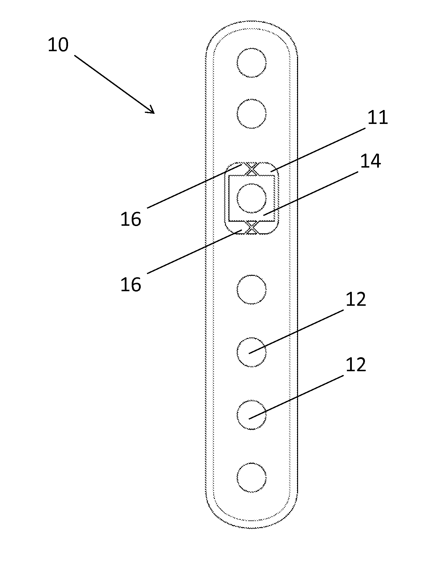
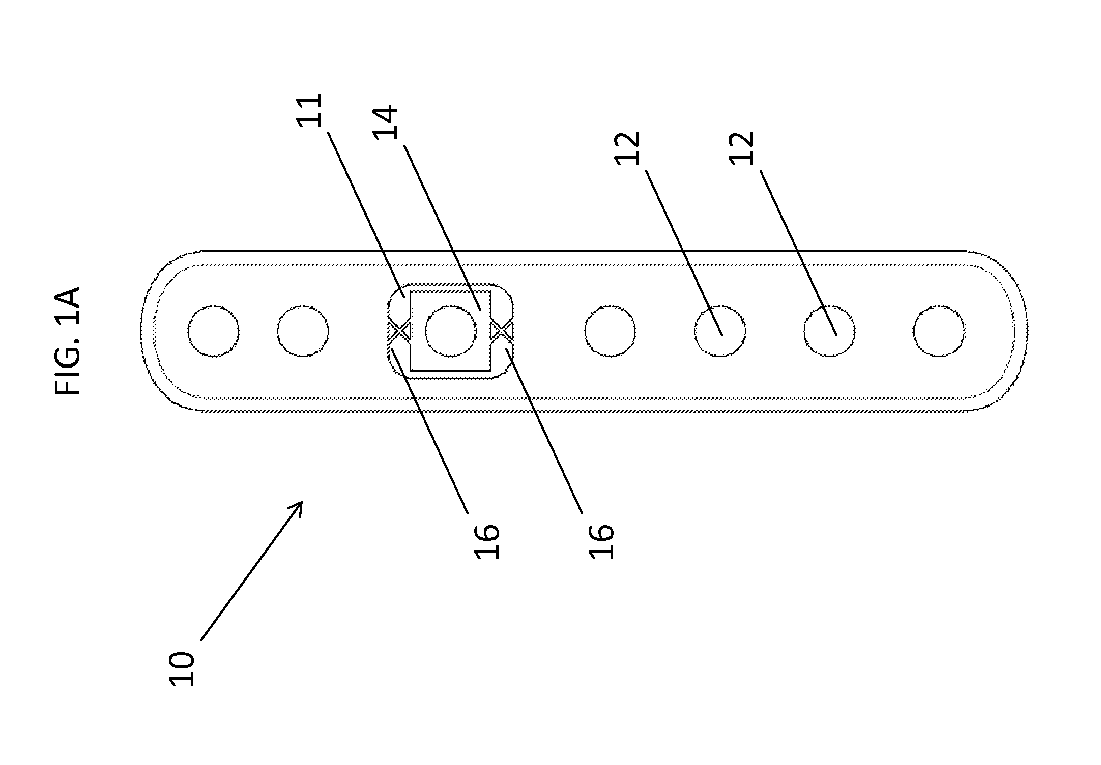
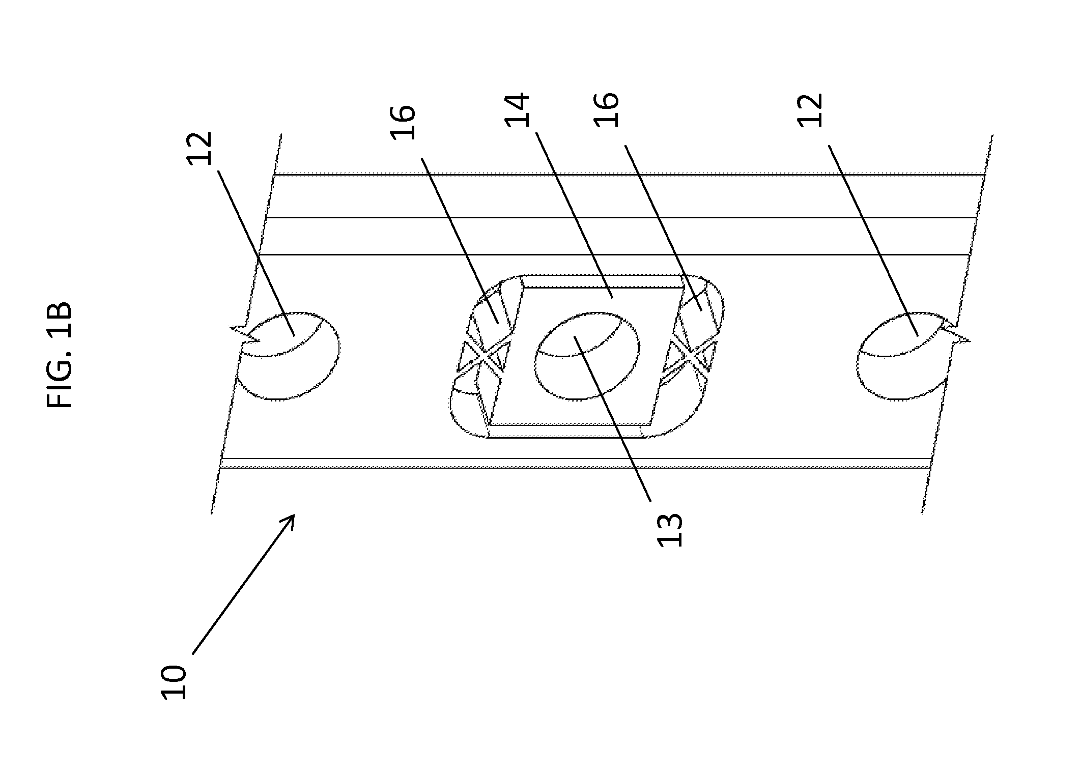
[0029]Referring to FIG. 1A there is shown a top view of one embodiment of bone fixation device 10. Bone fixation device 10 includes a bone contacting surface (not shown) and a surface facing away from the bone (shown in FIG. 1) with a plurality of holes or apertures 12 extending between the two surfaces. Holes or apertures 12 may be either threaded (for use with locking screws) or non-threaded (for use with non-locking or compression screws) and may be any suitable shape, s...


PUM


Abstract

A bone fixation device is disclosed that permits some movement of different portions of a fractured bone when the device is affixed thereto. Various embodiments are disclosed, including bone plates that have fixed holes and floating holes therethrough for receiving bone screws, and bone plates including oblong holes allowing for screw movement.

Description

CROSS-REFERENCE TO RELATED APPLICATIONS[0001]The present application claims the benefit of the filing date of U.S. Provisional Patent Application No. 61 / 549,439 filed on Oct. 20, 2011, the disclosure of which is hereby incorporated herein by reference.BACKGROUND OF THE INVENTION[0002]The present invention relates to devices used in the fixation of fractures in bones. More specifically, the present invention relates to a flexible bone plating system that rigidly fixes adjacent ends of a fractured bone while still allowing axial dynamization of the bone to promote healing of the fracture.[0003]Typical fixation of a fracture of a long bone with a bone plate requires making an incision in the tissue, reducing the fracture, placing a bone plate on the fractured bone, and securing the bone plate to the bone with fixation elements such as screws. The bone plate immobilizes the fracture and keeps the bone in a correct position so as to allow the fracture to heal. In certain cases, the bone ...

Claims


Application Information

Patent Timeline
Patent Type & Authority Applications(United States)
IPC IPC(8): A61B17/80A61B17/88
CPCA61B17/8085A61B17/8004A61B17/8042A61B17/8047
Inventor CREMER, AXEL BERNHARDCROZET, YVES STEPHANEEDELHAUSER, ADAM JOHNARELLANO, LUIS A.SYLVESTRE, PIERRE-LUCCHANG, ERICMORFING, NICKCHRISTEN, ALEXIS
Owner STRYKER EURO OPERATIONS HLDG LLC
Why Eureka
Try Eureka