Partially lighted t-bar

a t-bar and part-light technology, applied in the field of t-bars, to achieve the effect of long life, easy and inexpensive installation, and minimal energy utilization

Active Publication Date: 2016-03-17
JLC TECH IP LLC
View PDF7 Cites 22 Cited by
  • Summary
  • Abstract
  • Description
  • Claims
  • Application Information

AI Technical Summary

Benefits of technology

[0015]By providing partial lighted T-bars a maximum of lighting flexibility is provided. For instance, in a large room with a dropped ceiling and with multiple aisles between cubicles or other spaces, lighting can be provided to light the corridors between cubicles / spaces. Emergency lighting can be provided in the ceiling which could be a unique color, and could designate emergency pathways to follow when the building needs to be evacuated. For instance, T-bars adjacent a door which is not an exit could be illuminated red in an emergency. T-bars adjacent a door which is an appropriate exit can be lighted green. Lights in adjacent T-bars could also be caused to “chase” each other, by utilizing appropriate electronics coupled to power supplies of the T-bar lights, so that the lighting can appear to travel in a direction which should be followed when a person is evacuating a building. By providing partial lighted T-bars, such lighting can most effectively designate a corner where an evacuee needs to make a left or right hand turn to safely exit the building.OBJECTS OF THE INVENTION
[0016]Accordingly, a primary object of the present invention is to provide a T-bar which supports a light source on a lower side thereof and which includes partially lighted undersides and shorter lighted T-bars to facilitate a wide variety of lighting arrangements.
[0020]Another object of the present invention is to minimize energy utilized by a lighted building space.
[0022]Another object of the present invention is to provide a lighting system for a building space which is easy and inexpensive to install and which exhibits a long life.
[0023]Another object of the present invention is to provide a lighting system for a building which can easily be replaced and reconfigured.
[0024]Another object of the present invention is to provide an LED light source for mounting within a dropped ceiling of a building and which effectively dissipates heat from the LED light source for optimal service life.

Problems solved by technology

However, such a configuration only facilitates lighting oriented in a first direction perpendicular to the long T-bars.

Method used


Image

  • Partially lighted t-bar
  • Partially lighted t-bar
  • Partially lighted t-bar

Examples


Embodiment Construction

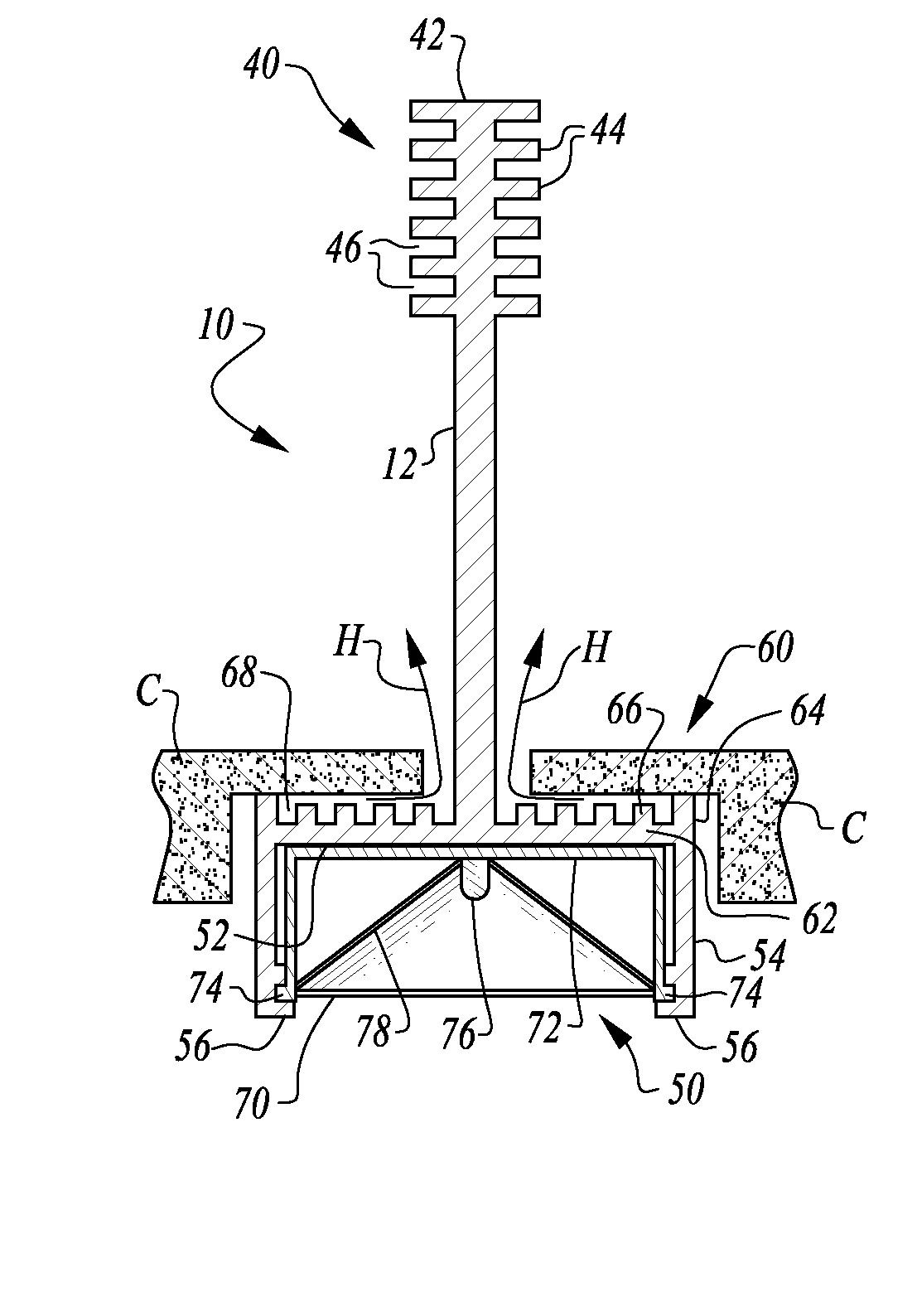
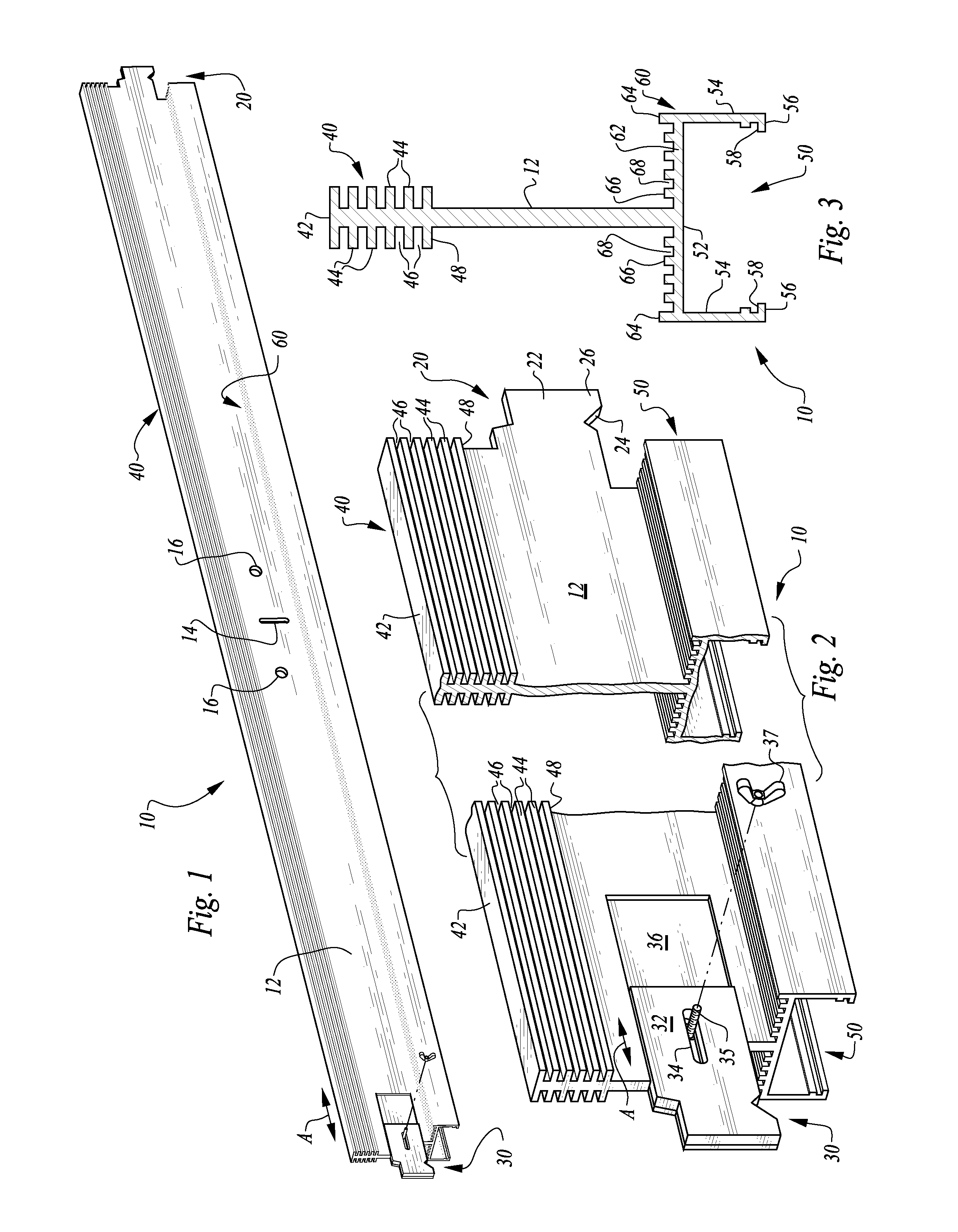
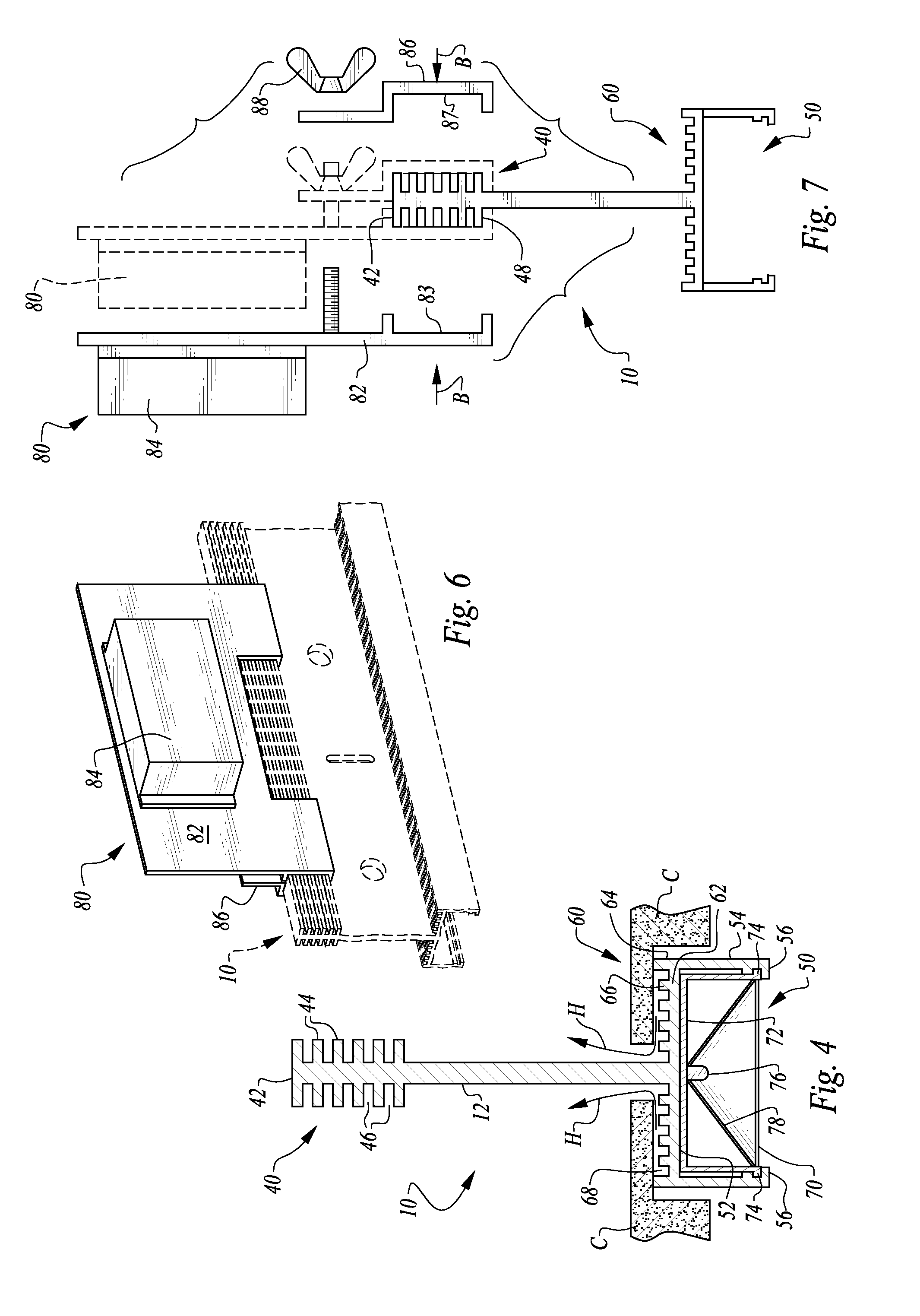
[0042]Referring to the drawings, wherein like reference numerals represent like parts throughout the various drawing figures, reference numeral 10 is directed to a basic fully lit T-bar (FIG. 1) forming a portion of a dropped ceiling system (FIG. 5) with the T-bar including a lighting module 70 (FIGS. 4, 5, 8 and 9) coupled to a lower end of the T-bar 10 for providing lighting in a space below the dropped ceiling system. The T-bar 10 includes heat dissipating structures including an upper heat sink 40 and lower heat sink 60 in this preferred embodiment for dissipating heat from the lighting module 70 or other heat sources adjacent the T-bar 10. A dropped ceiling system 100 (FIG. 15) can include partially lit T-bars 110 as well as fully lit T-bars 10 (FIG. 5) as well as long unlit (or lit) T-bars 410, short fully lit T-bars 210 (FIG. 14), short unlit T-bars 310 or non-lit T-bars 510, as examples, to facilitate a wide variety of suspended ceiling patterns.

[0043]In essence, and with pa...


PUM


Abstract

The partially lit T-bar includes a spine with a rest shelf at a lower portion thereof. The rest shelf supports adjacent ceiling tiles. The under surface of the rest shelf includes a lighting module on a portion and a plain unlit undersurface on other portions. Additional T-bars which are shorter, and typically fully lit or fully unlit and half the length of the partially lit T-bar are also provided which can attach at ends or near a midpoint of the partially lit T-bar and typically perpendicularly thereto. A great variety of lighting patterns in a dropped ceiling is thus facilitated. Each of the T-bars preferably also includes a heat sink on an upper portion of the spine and also preferably a lower heat sink on an upper portion of the rest shelf. Heat associated with the light element of the T-bar can thus be drawn away from a space below the ceiling.

Description

CROSS-REFERENCE TO RELATED APPLICATIONS[0001]This application claims benefit under Title 35, United States Code §119(e) of U.S. Provisional Application No. 62 / 082,760 filed on Nov. 21, 2014. This application is also a continuation-in-part of U.S. patent application Ser. No. 13 / 634,219 filed on Sep. 11, 2012, which is a national stage entry of PCT International Application No. PCT / US11 / 00455 with an international filing date of Mar. 11, 2011, which is a continuation of U.S. patent application Ser. No. 12 / 661,252 filed on Mar. 11, 2010 and issued as U.S. Pat. No. 8,177,385.FIELD OF THE INVENTION[0002]The following invention relates to T-bars for suspended ceilings, and particularly T-bars which include lighting therein. More particularly, this invention relates to T-bars and systems of T-bars where individual T-bar elements include a lit portion and an unlit portion, such as to achieve a large variety of lighting patterns in a suspended ceiling featuring lighted T-bars.BACKGROUND OF T...

Claims


Application Information

Patent Timeline
Patent Type & Authority Applications(United States)
IPC IPC(8): F21V21/03F21S8/06F21V29/76
CPCF21V21/03F21V29/76F21S8/063F21V29/713F21V33/006F21S8/02E04B9/006E04B9/064E04B9/122E04B9/28E04B9/241
Inventor PORCIATTI, SILVIO
Owner JLC TECH IP LLC
Why Eureka
Try Eureka