
Beam splitter and optical pickup device

a pickup device and beam splitter technology, applied in the field of beam splitter and optical pickup device, can solve the problems of increasing the number of parts, increasing the cost, and increasing the difficulty of adjustment, and achieve the effect of excellent recording and reproducing characteristics and small optical pickup devi

Inactive Publication Date: 2006-05-11
KONICA MINOLTA OPTO
View PDF9 Cites 1 Cited by
  • Summary
  • Abstract
  • Description
  • Claims
  • Application Information

AI Technical Summary

Benefits of technology

[0010] In the invention described in Structure 1, a beam splitter is provided with the illuminant light entering side prism where light from a light source enters and the reflected light entering side prism where light reflected on an information recording medium enters, and the multilayer coating having thereon plural specific laminated portions each having thereon a low refractive index layer, a medium refractive index layer, and a high refractive index layer, in this order from the reflected light entering side, is provided between the illuminant light entering side prism and the reflected light entering side prism, therefore, it is possible to make wavelength-dependency for reflectance, transmittance and reflection phase difference and incident-angle-dependency for reflectance, transmittance and for reflection phase difference of a beam splitter to be small.
[0013] In the invention described in Structure 2, reflectance Rs of S polarized light of reflected light outputted in the prescribed direction after light reflected on the information recording medium enters satisfies Rs≧90%, and reflectance Rp of P polarized light of reflected light outputted in the prescribed direction after light from a light source enters and reflectance R′p of P polarized light of reflected light outputted in the prescribed direction after light reflected on the information recording medium respectively satisfy 10%≦Rp≦40% and 10%≦R′p≦40%, thereby, it is possible to cause P polarized light having an appropriate amount of light to be reflected and to cause S polarized light having a large amount of light to be reflected.
[0037] In the invention described in Structure 13, excellent recording and reproducing characteristics are obtained, and the optical pickup device can be made small, because divergent light emitted from the light source enters the beam splitter.

Problems solved by technology

When employing this method, there is caused a problem of cost increase, because adjustment becomes more difficult and the number of parts is increased.
As stated above, it has been impossible to make incident-angle-dependency for reflectance, transmittance and reflection phase difference to be small, without using the special structure, and it has been impossible to make incident-angle-dependency for reflectance, transmittance and reflection phase difference to be small in an ordinary structure, which has been a problem.
However, the beam splitter satisfying the aforesaid conditions and an optical pickup device employing that beam splitter have not been suggested in the past.

Method used


Image

  • Beam splitter and optical pickup device
  • Beam splitter and optical pickup device
  • Beam splitter and optical pickup device

Examples


first embodiment

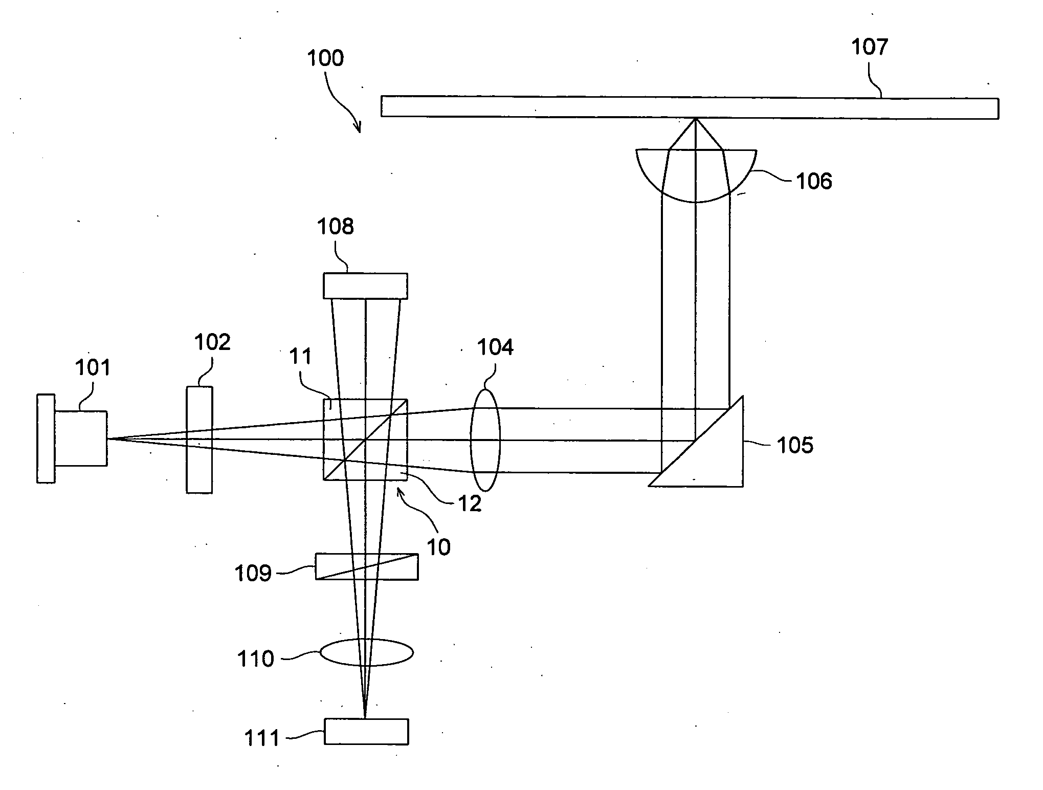
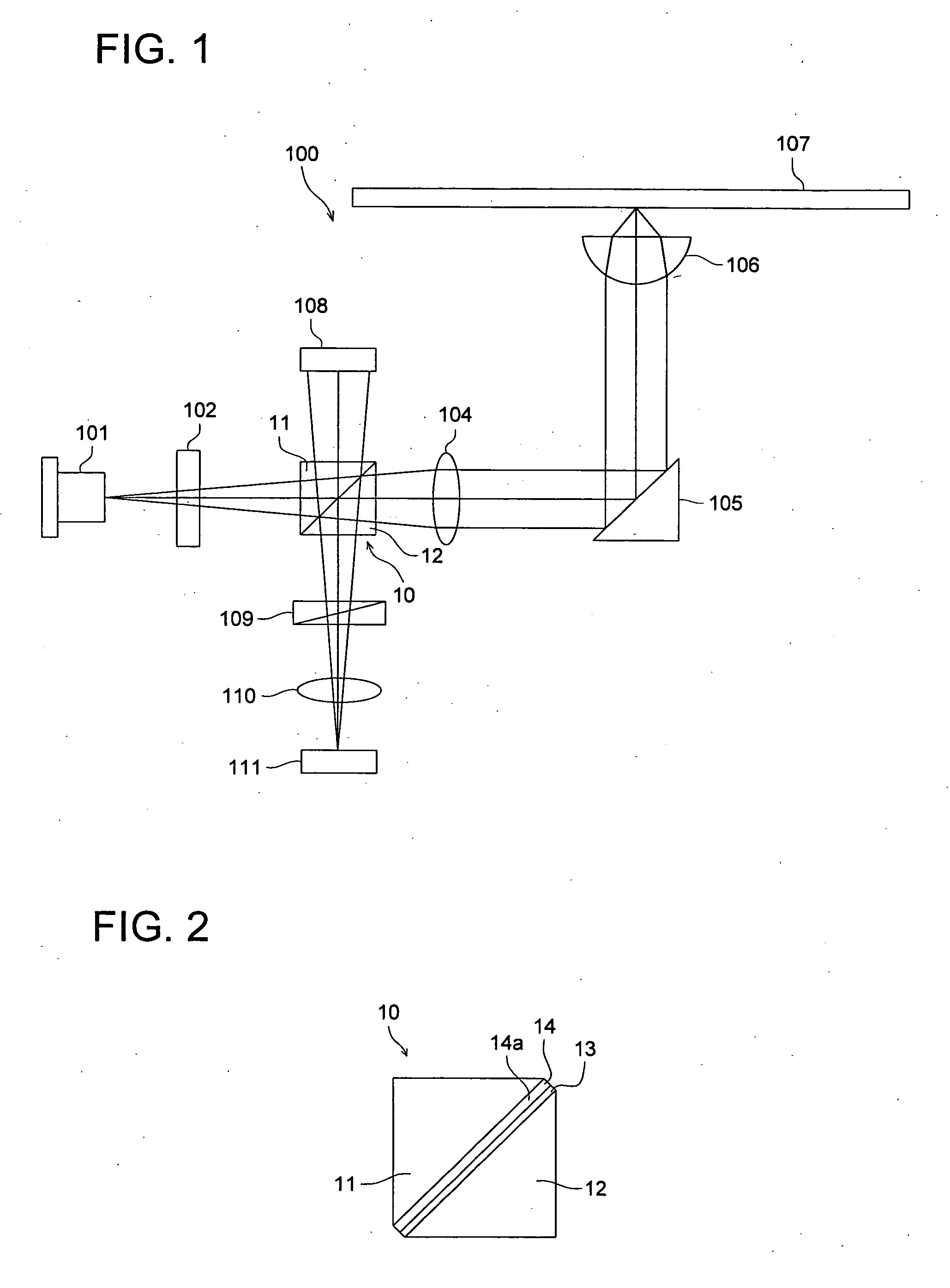
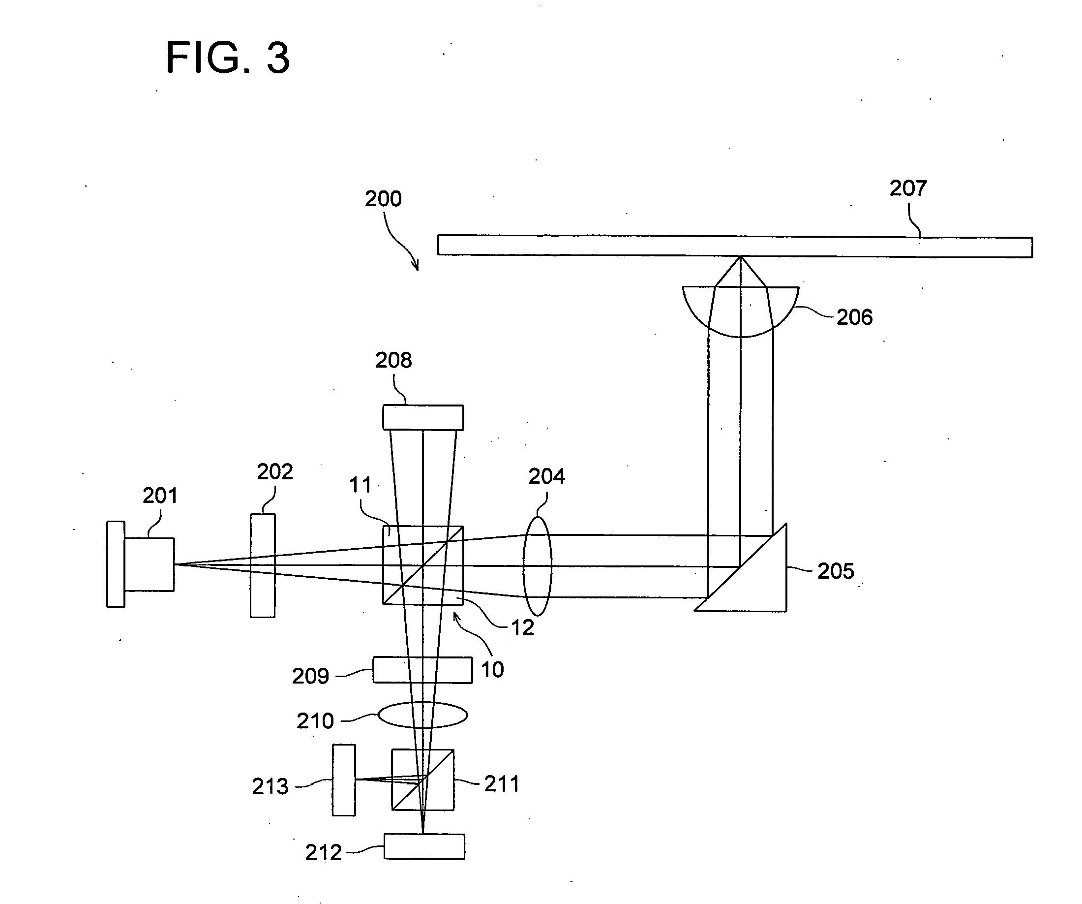
[0059]FIG. 1 is a diagram showing schematically optical pickup device 100 relating to the first embodiment to which the invention is applied.

[0060] The optical pickup device 100 is a device wherein information is recorded on a magneto-optical disc when irradiating the magneto-optical disc with a laser beam to give energy of Curie point or higher to the magneto-optical disc and thereby to give magnetism corresponding to the direction of magnetism of external magnetic field in the direction perpendicular to the magneto-optical disc, while, information is reproduced by detecting changes in P polarized light component and S polarized light component of reflected light coming from the magneto-optical disc, by utilizing that a plane of polarization of a laser beam is slightly rotated by Kerr effect depending on the direction of magnetism of magneto-optical disc 107.

[0061] The optical pickup device 100 of the present embodiment is provided with laser diode 101 representing a light source...

second embodiment

[0090] Next, Second Embodiment to which the invention is applied will be explained.

[0091] In the present embodiment, structures of the beam splitter excluding that of a multilayer film are the same as those in the First Embodiment, and therefore, explanation for the similar structures will be omitted.

[0092] The multilayer film of the beam splitter relating to the Second Embodiment will be explained below.

[0093] Multilayer film 13 in the present embodiment is a coated film provided on a slant of the reflected light entering side prism 12, as in the First Embodiment, and it is formed to be of the structure shown in Table 2.

TABLE 2RefractiveLayerNo.indexthickness (nm)Illuminant light entering1.64side prism (S-TIM22)UV curing adhesive agent1.620MgF21.38116.5819Ta2O52.04173.9718Al2O31.61129.0217MgF21.38172.3416Ta2O52.0465.2115Al2O31.61109.3514MgF21.38133.9613Ta2O52.0465.9812Al2O31.61128.4611MgF21.38112.1810Ta2O52.0462.269Al2O31.61143.598MgF21.3872.67Ta2O52.0469.896Al2O31.61146.695Ta...

third embodiment

[0103] Next, Third Embodiment to which the invention is applied will be explained.

[0104] In the present embodiment, structures of the beam splitter excluding that of a multilayer film are the same as those in the First Embodiment, and therefore, explanation for the similar structures will be omitted.

[0105] The multilayer film of the beam splitter relating to the Third Embodiment will be explained below.

[0106] Multilayer film 13 in the present embodiment is a coated film provided on a slant of the reflected light entering side prism 12, as in the First Embodiment, and it is formed to be of the structure shown in Table 3.

TABLE 3RefractiveLayerNo.indexthickness (nm)Illuminant light entering1.64side prism (S-TIM22)UV curing adhesive agent1.622SiO21.45187.5721TiO22.2623.6820SiO21.4594.1519Al2O31.61116.0318TiO22.2626.8417SiO21.45156.316TiO22.2644.8715Al2O31.61120.7714SiO21.45112.4113TiO22.2651.2512Al2O31.61144.2111SiO21.4560.7410TiO22.2670.949Al2O31.61137.868SiO21.4549.387TiO22.2679....


PUM


Abstract

A beam splitter, comprises: a light source light entering side prism to which a light from a light source enters; a reflected light entering side prism to which a reflected light from an information recording medium enters; a multi layer film provided between the light source light entering side prism and the reflected light entering side prism, wherein the multi layer film comprises a plurality of specific laminated sections each of which comprises a low refractive index layer, a medium refractive index layer, and a high refractive index layer in this order from the reflected light entering side.

Description

[0001] This application is based on Japanese Patent application No. 2004-325167 filed on Nov. 9, 2004, in Japanese Patent Office, the entire content of which is hereby incorporated by reference. BACKGROUND OF THE INVENTION [0002] The present invention relates to a beam splitter and an optical pickup device equipped with the same. [0003] A movement toward high performance and miniaturization of an optical pickup device used for a magneto-optical disc and others have been advanced in recent years. As one of the methods for miniaturization, there is given a method wherein a light flux emitted from a laser light source enters a beam splitter as finite light, and after being transmitted through a beam splitter, it is converted by a collimator lens into infinite light to enter an objective lens. There is further a method wherein a collimator lens is omitted, and a light flux enters an objective lens as finite light. When causing finite light to enter a beam splitter, it is necessary to ma...

Claims


Application Information

Patent Timeline
IPC IPC(8): G11B7/00
CPCG02B5/3041G02B27/283G11B7/1395G11B11/10543
Inventor HIRAYAMA, HIROSHI
Owner KONICA MINOLTA OPTO
Learn More