
Light emitting diode assembly, backlight module, liquid crystal display and illumination device

a technology of light-emitting diodes and backlight modules, which is applied in the direction of lighting and heating apparatus, semiconductor devices for light sources, instruments, etc., can solve the problems of lens use and structural complexity, and achieve the effect of simple structur

Active Publication Date: 2016-01-26
BOE TECH GRP CO LTD +1
View PDF7 Cites 0 Cited by
  • Summary
  • Abstract
  • Description
  • Claims
  • Application Information

AI Technical Summary

Benefits of technology

[0006]The present disclosure provides a light emitting diode assembly, a backlight module, a liquid crystal display and an illumination device, wherein the LED assembly has a larger light exit angle and a simple structure.
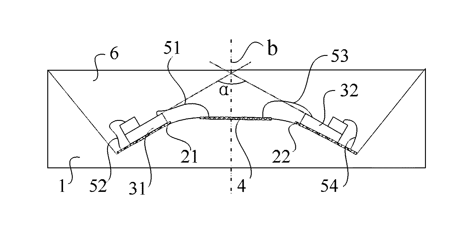
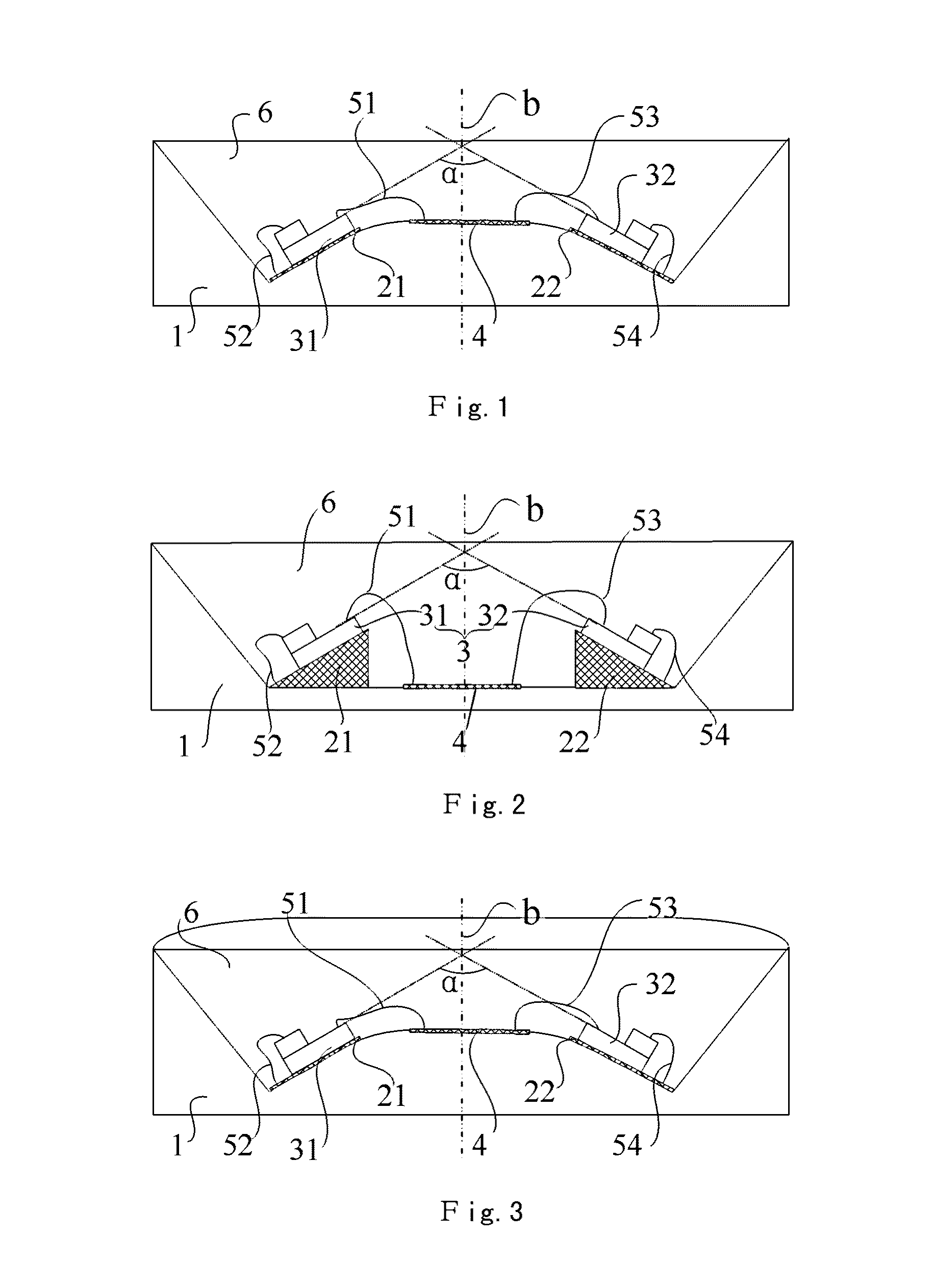
[0011]In the above LED assembly, the bottom surface of the mounting groove of the lamp base is mounted with at least one pair of LED dies, two LED dies in each pair of LED dies are disposed symmetrically about an axis of the mounting groove, and among angles formed by intersection of planes where light exit surfaces of the two LED dies lie, an angle facing the bottom surface of the mounting groove is greater than 0 degree and less than 180 degrees. Therefore, a light emitting scope of each LED die deviates in a direction away from the other LED die so that the light exit angle of the entire light emitting diode assembly is enabled to expand.
[0012]Therefore, the light emitting diode assembly may expand its light exit angle without using a lens and exhibits a simple structure.

Problems solved by technology

However, this method requires use of the lens and is structurally complicated.

Method used


Image

  • Light emitting diode assembly, backlight module, liquid crystal display and illumination device
  • Light emitting diode assembly, backlight module, liquid crystal display and illumination device
  • Light emitting diode assembly, backlight module, liquid crystal display and illumination device

Examples


Embodiment Construction

[0027]The following clearly and completely describes the technical solutions in the embodiments of the present disclosure with reference to the accompanying drawings in the embodiments of the present disclosure. Obviously, the described embodiments are merely a part rather than all of the embodiments of the present disclosure. All other embodiments obtained by persons of ordinary skill in the art based on the embodiments of the present disclosure without creative efforts shall fall within the protection scope of the present disclosure.

[0028]Please refer to FIG. 1 and FIG. 2. FIG. 1 is a structural schematic view of a light emitting diode assembly according to an embodiment of the present disclosure; FIG. 2 is a structural schematic view of a light emitting diode assembly according to another embodiment of the present disclosure.

[0029]The light emitting diode assembly according to the embodiment of the present disclosure comprises a lamp base 1 having a mounting groove; and at least ...


PUM

PropertyMeasurementUnit
angleaaaaaaaaaa
angleaaaaaaaaaa
angleaaaaaaaaaa

Abstract

The present disclosure relates to the technical field of light emission of an LED and discloses a light emitting diode assembly, a backlight module, a liquid crystal display and an illumination device. The LED assembly comprises a lamp base and at least one pair of LED dies. The lamp base has a mounting groove. A pair of the LED dies are mounted at a bottom surface of the mounting groove, and two LED dies in the pair of LED dies are disposed symmetrically about an axis of the mounting groove. Among angles formed by intersection of planes where light exit surfaces of the two LED dies lie, an angle facing the bottom surface of the mounting groove is greater than 0 degree and less than 180 degrees. The light emitting diode assembly has a larger light exit angle and exhibits a simple structure.

Description

RELATED APPLICATIONS[0001]The present application claims the benefit of Chinese Patent Application No. 201410221693.7, filed on May 23, 2014, the entire disclosure of which is incorporated herein by reference.BACKGROUND OF THE DISCLOSURE[0002]1. Field of the Disclosure[0003]The present disclosure relates to the technical field of light emission of an LED, and particularly to a light emitting diode assembly, a backlight module, a liquid crystal display and an illumination device.[0004]2. Description of the Prior Art[0005]Currently a mainstream method of increasing a light exit angle of an LED is to add a lens at a surface of the LED. For example, N plus of Japan holds a patent application in this regard. The method of adding the lens at the surface of the LED may expand the light exit angle and can ensure even distribution of light intensity. However, this method requires use of the lens and is structurally complicated.SUMMARY OF THE DISCLOSURE[0006]The present disclosure provides a ...

Claims


Application Information

Patent Timeline
Patent Type & Authority Patents(United States)
IPC IPC(8): H01L33/48G02F1/1335F21K99/00F21V19/00H01L25/075F21Y115/10
CPCH01L25/0753F21K9/00F21K9/1355F21K9/1375F21K9/175F21K9/30G02F1/133603H01L33/48H01L33/483H01L33/486F21V19/001Y10S362/80H01L2224/48091H01L2224/49107H01L33/58F21Y2115/10F21Y2107/10F21K9/23F21K9/27H01L2924/00014
Inventor WANG, TAO
Owner BOE TECH GRP CO LTD
Learn More