Methods, systems and apparatuses for network assisted interference cancellation and suppression in long-term evolution (LTE) systems

a technology of network assisted interference and suppression, applied in the field of wireless communication, can solve the problems of increasing the overall interference landscape and the cost of deployment, and achieve the effect of suppressing the interferen

Inactive Publication Date: 2016-03-17
INTERDIGITAL PATENT HLDG INC
View PDF6 Cites 88 Cited by
  • Summary
  • Abstract
  • Description
  • Claims
  • Application Information

AI Technical Summary

Benefits of technology

[0018]A method implemented by a Wireless Transmit/Receive Unit (WTRU) includes receiving a DeModulation Interference Measurement (DM-IM) resource, determining an interference measurement based on the DM-IM resource, and demodulating a received signal based on the interference measurement. An interference is suppressed based on the interference measurement. At least one DM-IM resource is located in a Physical Resource Block (PRB). The at least one DM-IM resource is located in a PRB allocated for the WTRU. The DM-IM resource is a plurality of DM-IM resources, the plurality of DM-IM resources form a DM-IM pattern, and the DM-IM pattern is located on at least one of a Physical Downlink Shared Channel (PDSCH) and/or an enhanced Physical Downlink Shared Channel (E-PDSCH) of at least one Long Term Evolution (LTE) subframe. The DM-IM resources are different for different Physical Resource Blocks (PRB) in the LTE subframe. The DM-IM is located in a Long Term Evolution (LTE) Resource Block (RB), and the method includes adjusting a DM-IM pattern based on at least one of a frame number associated with the LTE RB, a subframe number associated with the LTE RB, and/or an RB index associated with the LTE RB. A plurality of DM-IM resources is received, and the DM-IM resources are adjusted in respective LTE subframes based on a higher layer signaling. Locating a DM-IM resource associated with the WTRU based on a cell specific identifier associated with a cell serving the WTRU is performed.
[0019]A Wireless Transmit/Receive Unit (WTRU) includes a receiver configured to receive a DeModulation Interference Measurement (DM-IM) resource, and a processor configured to determine an interference measurement based on the DM-IM resource, and demodulate a received ...

Problems solved by technology

Such new deployments may come at the cost ...

Method used


Image

  • Methods, systems and apparatuses for network assisted interference cancellation and suppression in long-term evolution (LTE) systems
  • Methods, systems and apparatuses for network assisted interference cancellation and suppression in long-term evolution (LTE) systems
  • Methods, systems and apparatuses for network assisted interference cancellation and suppression in long-term evolution (LTE) systems

Examples


example architecture

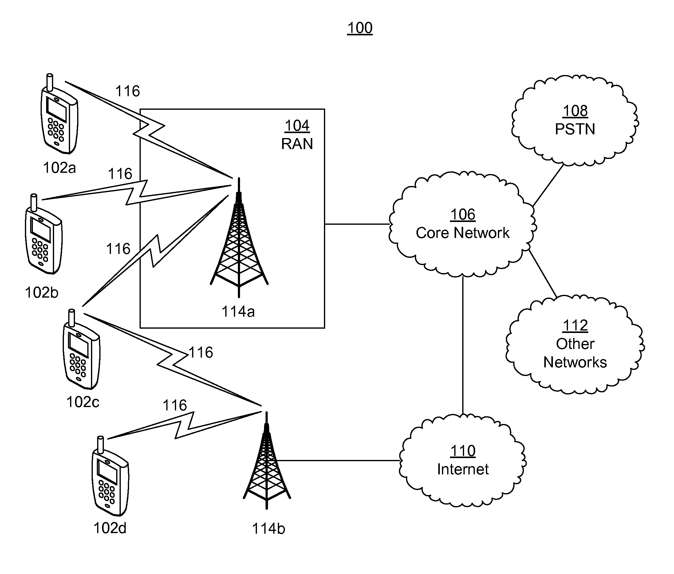
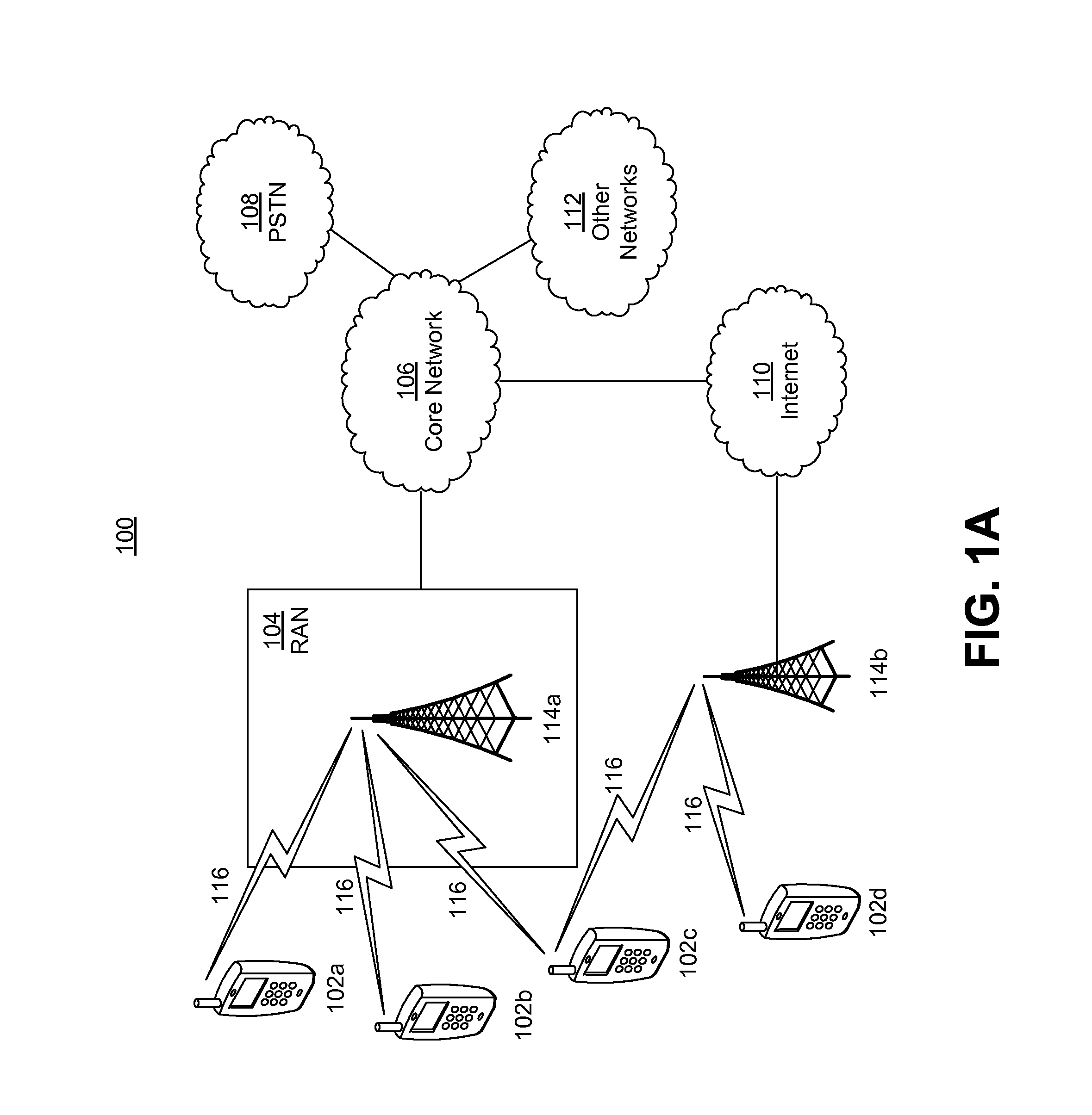
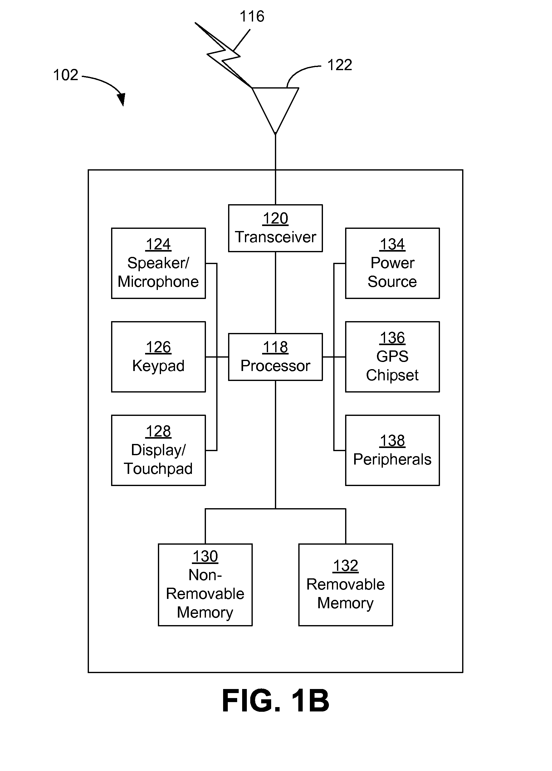
[0036]When referred to herein, the terms “user equipment” and its abbreviation “UE” may mean (i) a wireless transmit and / or receive unit (WTRU), such as described infra; (ii) any of a number of embodiments of a WTRU, such as described infra; (iii) a wireless capable and / or wired capable (e.g., tetherable) device configured with, inter alia, some or all structures and functionality of a WTRU, such as described infra; (iii) a wireless capable and / or wired capable device configured with less than all structures and functionality of a WTRU, such as described infra; or (iv) the like. Details of an example WTRU, which may be representative of any UE recited herein, are provided below with respect to FIGS. 1A-1C.

[0037]When referred to herein, the terms “evolved Node-B” and its abbreviations “eNB” and “eNode-B” may mean (i) a base station, such as described infra; (ii) any of a number of embodiments of a base station, such as described infra; (iii) a device configured with, inter alia, some...


PUM


Abstract

A method implemented by a Wireless Transmit/Receive Unit (WTRU) includes receiving a DeModulation Interference Measurement (DM-IM) resource, determining an interference measurement based on the DM-IM resource, and demodulating a received signal based on the interference measurement. An interference is suppressed based on the interference measurement. At least one DM-IM resource is located in a Physical Resource Block (PRB). The DM-IM resource is located in a PRB allocated for the WTRU. The DM-IM resource is a plurality of DM-IM resources which form a DM-IM pattern, and the DM-IM pattern is located on a Physical Downlink Shared Channel (PDSCH) and/or an enhanced Physical Downlink Shared Channel (E-PDSCH) of at least one Long Term Evolution (LTE) subframe. The DM-IM resources are different for different Physical Resource Blocks (PRB) in the LTE subframe. The DM-IM is located in a Long Term Evolution (LTE) Resource Block (RB), and the DM-IM pattern is adjusted.

Description

BACKGROUND[0001]1. Field[0002]This application is related to wireless communication.[0003]2. Related Art[0004]Long Term Evolution (LTE)[0005]LTE: Single Carrier[0006]3rd Generation Partnership Project (3GPP) long term evolution (LTE) Release 8 and / or 9 (LTE Rel-8 / 9) may support up to 100 Mbps in a Downlink (DL), and 50 Mbps in an Uplink (UL) for a 2×2 configuration. The LTE DL transmission scheme is based on an Orthogonal Frequency Division Multiple Access (OFDMA) air interface.[0007]LTE Rel-8 / 9 and / or release 10 (collectively “LTE Rel-8 / 9 / 10”) systems support scalable transmission bandwidths (e.g., for purposes of flexible deployment, etc.). Such scalable transmission bandwidths may include, for example, bandwidths of 1.4, 2.5, 5, 10, 15 and 20 megahertz (MHz).[0008]In LTE Rel-8 / 9 (and as applicable to LTE Rel-10), each radio frame has a duration of 10 milliseconds (ms), and consists of 10 subframe each of which is 1 ms. Each subframe consists of 2 timeslots of 0.5 ms each. There m...

Claims


Application Information

Patent Timeline
IPC IPC(8): H04W24/10H04W72/08
CPCH04W72/082H04W24/10H04L5/0053H04L5/0092H04J11/005H04L5/0023H04L5/001H04L5/0048H04L5/143H04L5/1453H04L5/0082H04L27/0008H04L27/0012H04L27/2067H04L27/362H04W24/08H04W48/12H04L5/0007H04W72/541
Inventor MARINIER, PAULLEE, MOON-ILTOOHER, J. PATRICKRUDOLF, MARIANNAYEB NAZAR, SHAHROKHSTERN-BERKOWITZ, JANET A.
Owner INTERDIGITAL PATENT HLDG INC
Why Eureka
Try Eureka