Interface for control of a foldable wing on an aircraft

a technology of foldable wings and control interfaces, which is applied in the direction of process and machine control, instruments, navigation instruments, etc., can solve the problems of insufficient intuitiveness of control interfaces, limited maximum aircraft span, and difficulty for pilots to clearly determine the information being conveyed

Active Publication Date: 2016-03-31
AIRBUS OPERATIONS LTD
View PDF4 Cites 24 Cited by
  • Summary
  • Abstract
  • Description
  • Claims
  • Application Information

AI Technical Summary

Benefits of technology

The patent text is saying that the outer part of the wing of an aircraft should not have any control surfaces. This is because it doesn't need any infrastructure to operate the control surface, which could be complicated. The technical effect of this is that it simplifies the design of the wing and reduces the complexity of the aircraft.

Problems solved by technology

The technical problem addressed in this patent is the complexity and difficulty of controlling foldable wings on aircraft, which can make it hard for pilots to determine the information being conveyed and can result in insufficiently intuitive and ergonomic interfaces. The invention seeks to improve the control interface for foldable wings to make it easier for pilots to operate the aircraft and benefit from the larger wing span in flight.

Method used


Image

  • Interface for control of a foldable wing on an aircraft
  • Interface for control of a foldable wing on an aircraft
  • Interface for control of a foldable wing on an aircraft

Examples


Embodiment Construction

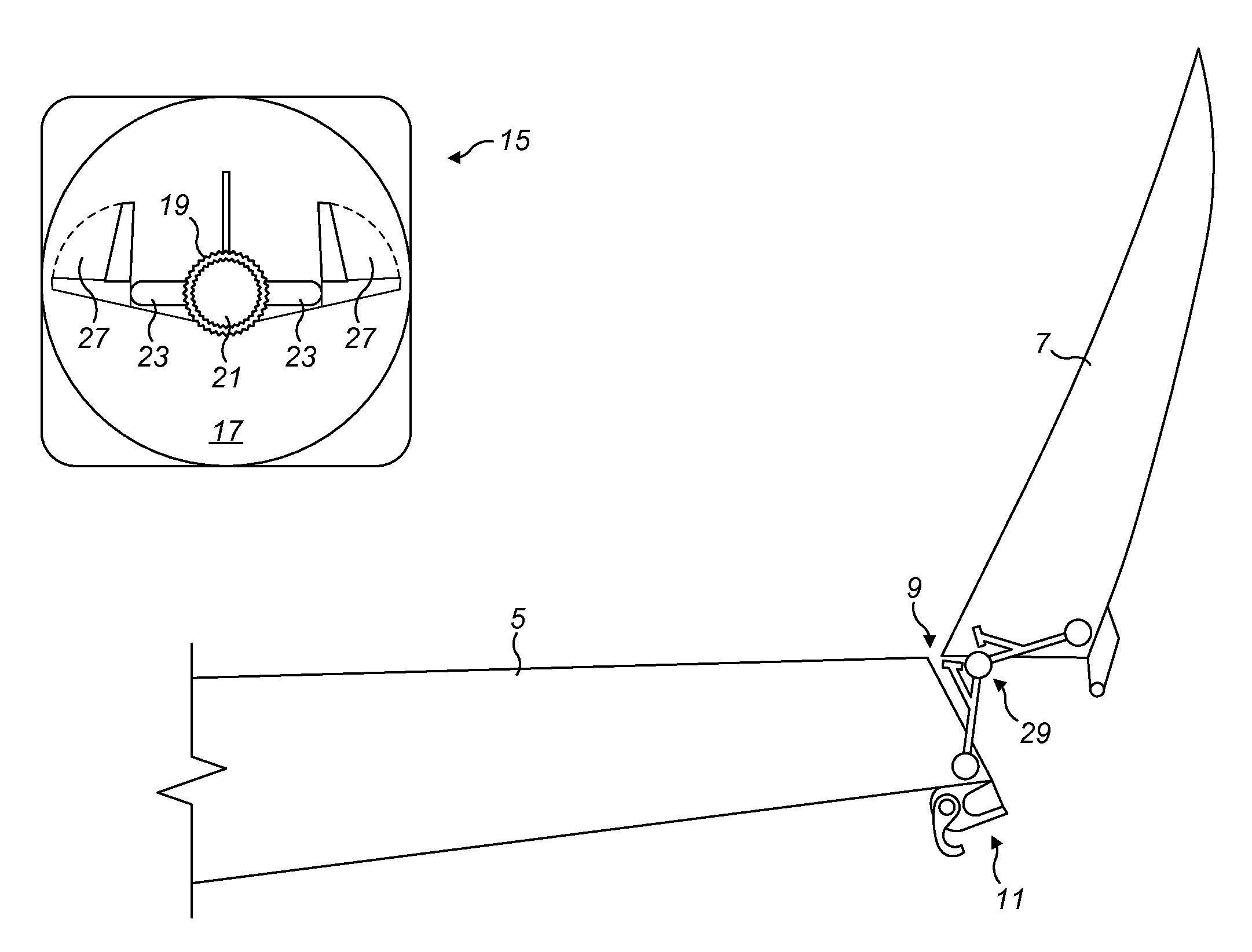
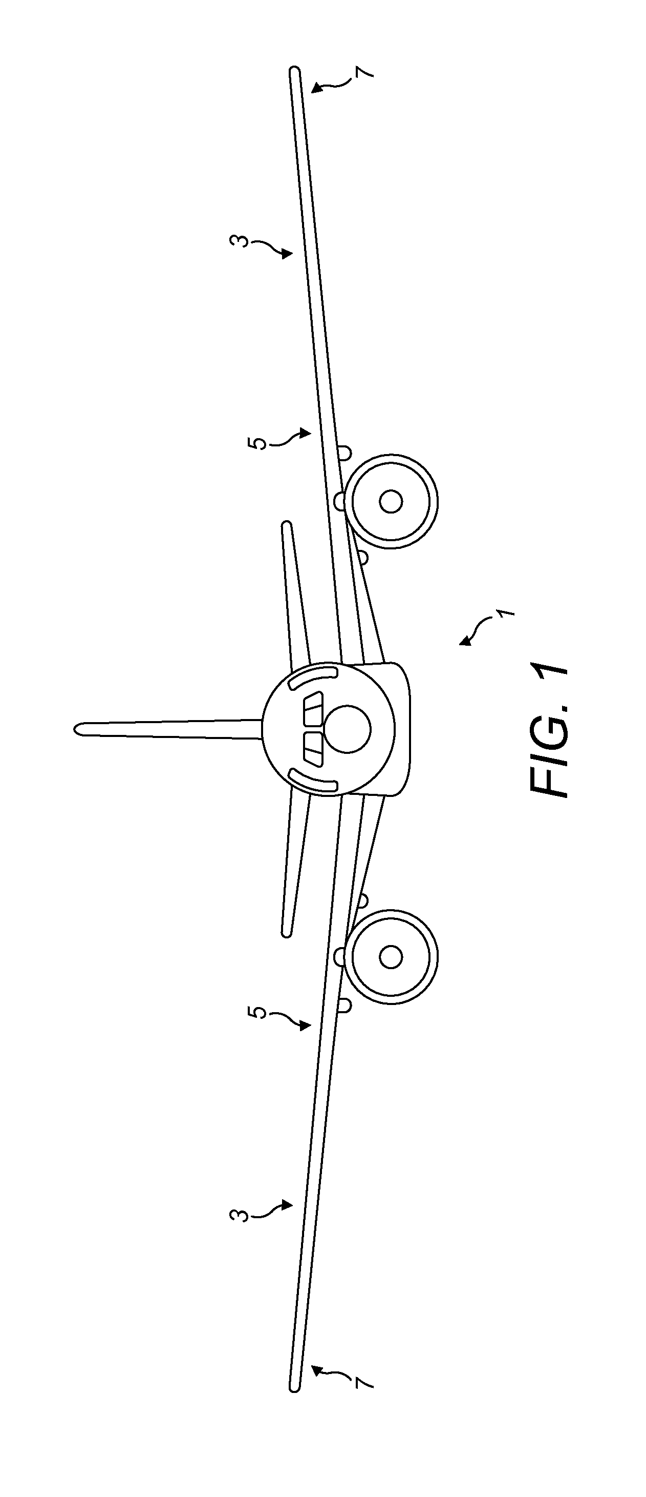
[0039]FIG. 1 is a front view of an aircraft 1 according to a first embodiment of the invention. The aircraft 1 has two wings 3. Each wing 3 comprises an inner region 5 and an outer region 7. The inner region 5 extends from the wing root to a junction with the outer region 7. The outer region 7 is in the form of a planar tip extension. Other embodiments of the invention (not shown) incorporate other types of outer region, for example incorporating wing tip devices such as winglets.

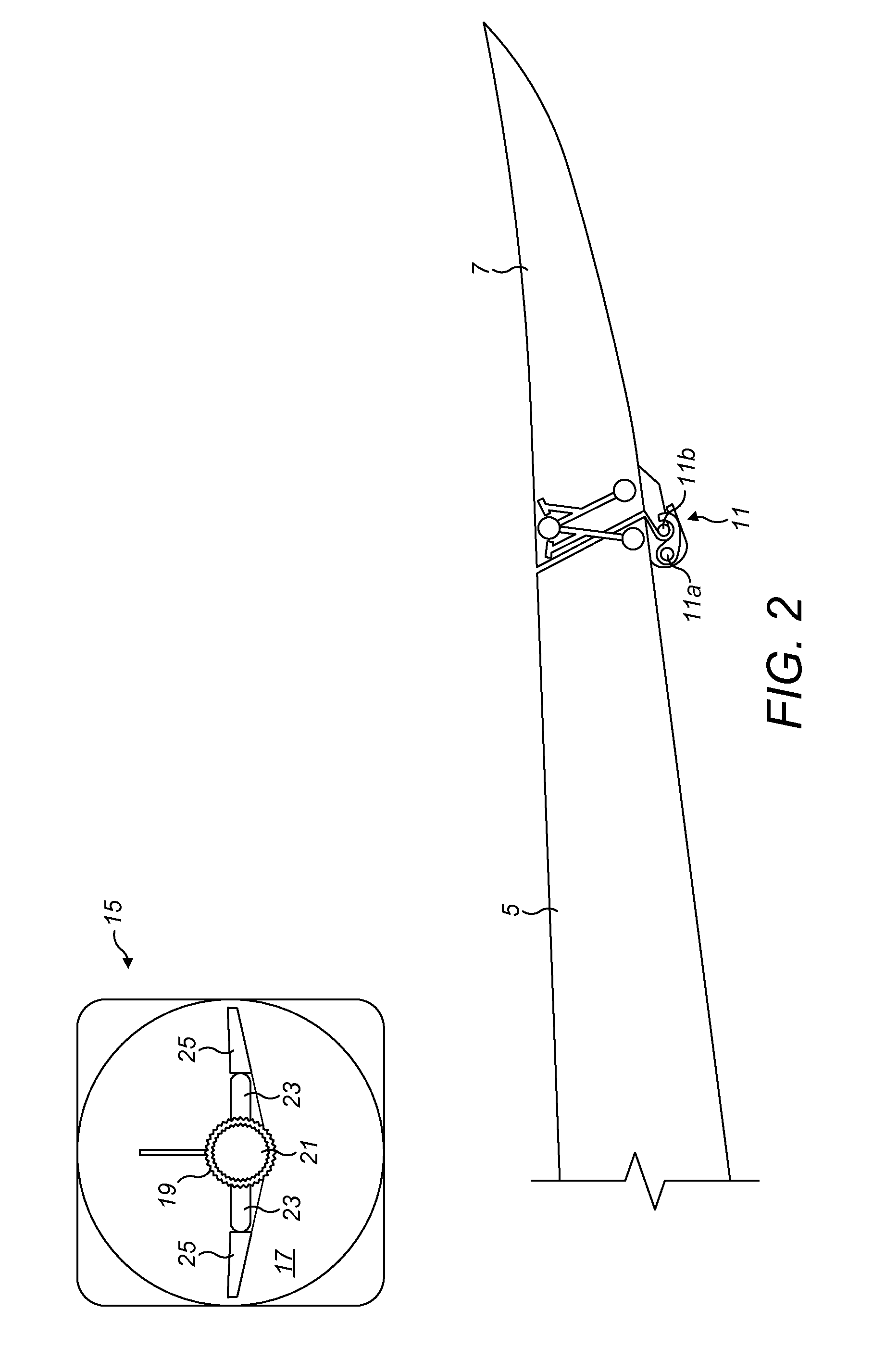
[0040]The tip extension 7 is mounted along a hinge line (not shown in FIG. 1) at the junction with the inner region, and is rotatable about that hinge between a flight configuration (shown in FIGS. 1 and 2) and a ground configuration (described with reference to FIGS. 3 to 5). In the ground configuration the wing tip extension 7 is rotated upwardly, thereby reducing the span of the aircraft 1. This enables the aircraft 1 (with the wing tip extension in the ground configuration) to meet existing airport gate...


PUM


Abstract

An aircraft comprises a foldable wing, the wing comprising an inner region and an outer region, such as a wing tip. The outer region is moveable relative to the inner region between a flight configuration and a ground configuration in which the span is reduced. The aircraft comprises a control system and a control interface. The control interface comprises a selector for selecting the desired configuration of the outer region, and is arrange to provide: a first output, such as a light, when the flight configuration is selected and the outer region is in the flight configuration; a second output, such an amber light, when the ground configuration is selected and the outer region is in the ground configuration; and a third output, such as a red light, when the outer region is not in the selected configuration.

Description


Claims


Application Information

Patent Timeline
Owner AIRBUS OPERATIONS LTD
Why Eureka
Try Eureka