
Reducing write amplification in solid-state drives by separating allocation of relocate writes from user writes

a write amplification and solid-state drive technology, applied in the field of data storage systems, can solve the problems of invalidated data location not being reused, the organization of flash blocks into raid-like stripes is more complex, and the operation is typically one order of magnitude faster

Inactive Publication Date: 2016-03-31
IBM CORP
View PDF1 Cites 29 Cited by
  • Summary
  • Abstract
  • Description
  • Claims
  • Application Information

AI Technical Summary

Benefits of technology

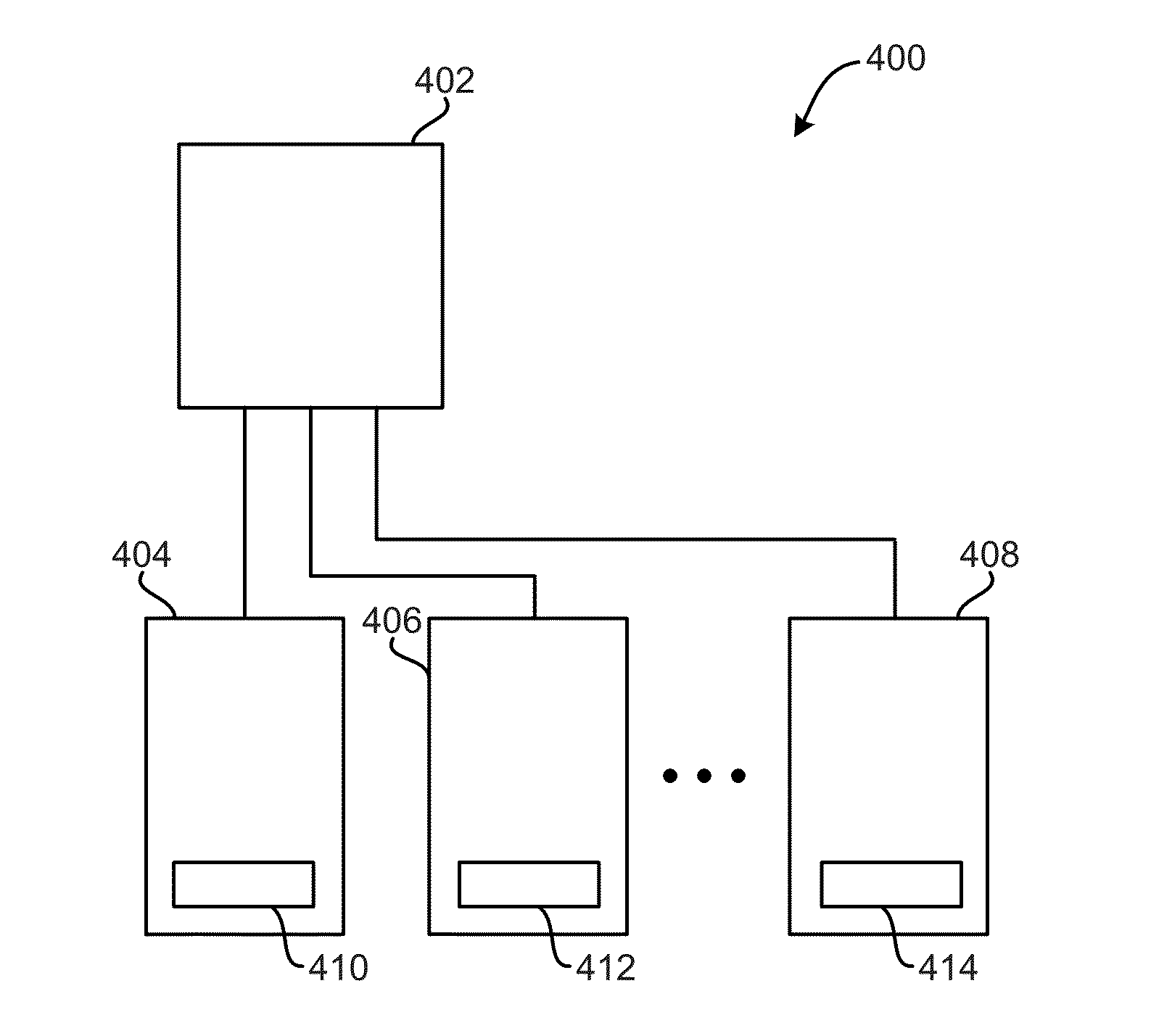
This patent describes a method for maintaining two logical erase blocks in a computer system, one for user writes and another for relocate writes. The method allows for simultaneous processing of two data streams, with one stream sent to the user write block and the other stream sent to the relocate write block. This ensures efficient processing and reduces processing delays.

Problems solved by technology

Moreover, page read operations are typically one order of magnitude faster than write operations and latency neither depends on the current nor the previous location of operations.
While the addition of ECC in pages is relatively straightforward, the organization of flash blocks into RAID-like stripes is more complex.
In this approach, a flash page overwrite will result in writing the flash page data to a new location in flash, marking the old copy of the flash page data as invalid, and then updating the mapping information.
Due to the limitations of current NAND flash technology, an invalidated data location cannot be reused until the entire block it belongs to has been erased.
Garbage collection of a block is typically deferred for as long as possible to maximize the amount of invalidated data in block, and thus reduce the number of valid pages that must be relocated, as relocated data causes additional write operations, and thereby increases write amplification.

Method used


Image

  • Reducing write amplification in solid-state drives by separating allocation of relocate writes from user writes
  • Reducing write amplification in solid-state drives by separating allocation of relocate writes from user writes
  • Reducing write amplification in solid-state drives by separating allocation of relocate writes from user writes

Examples


Embodiment Construction

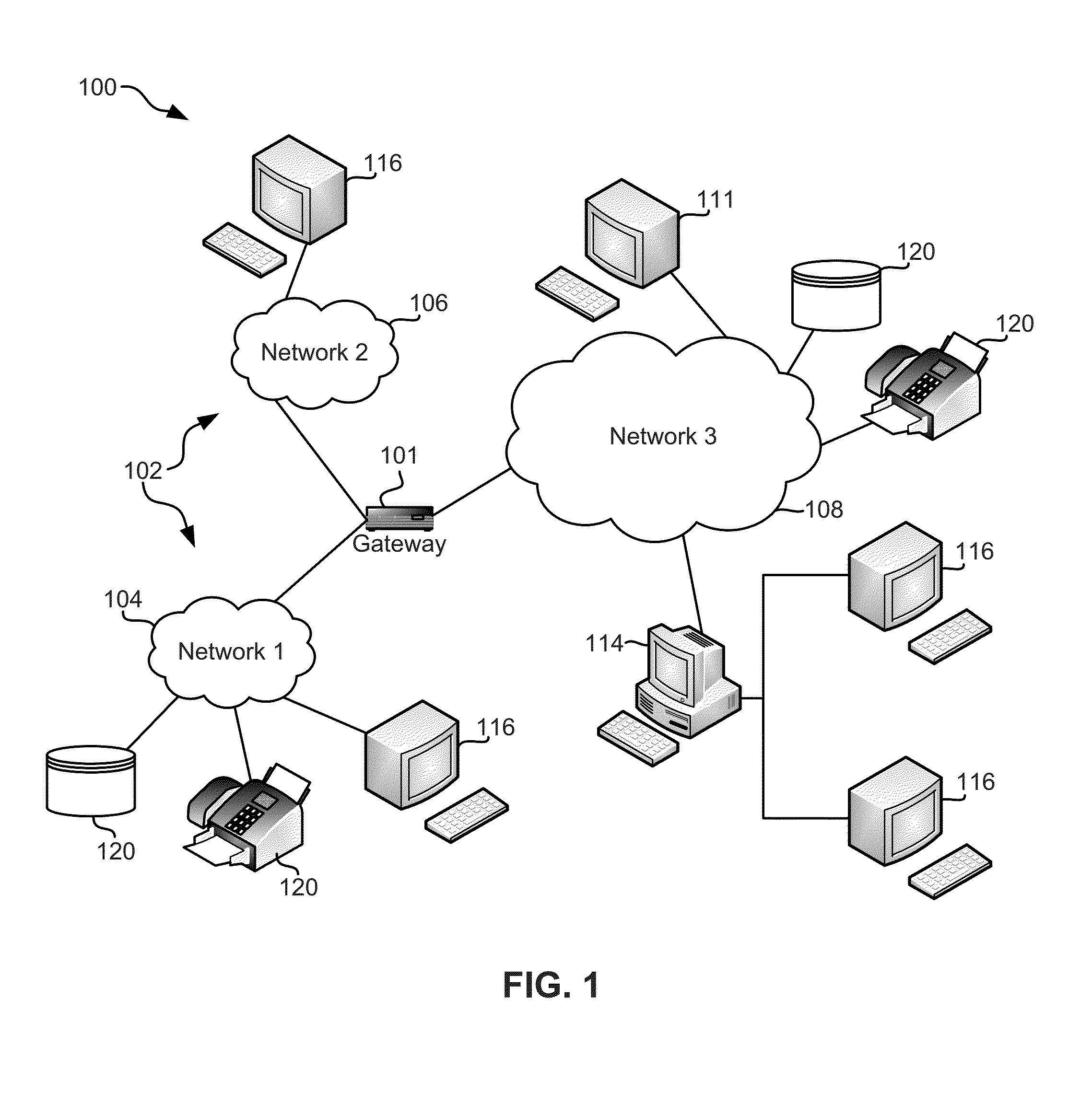
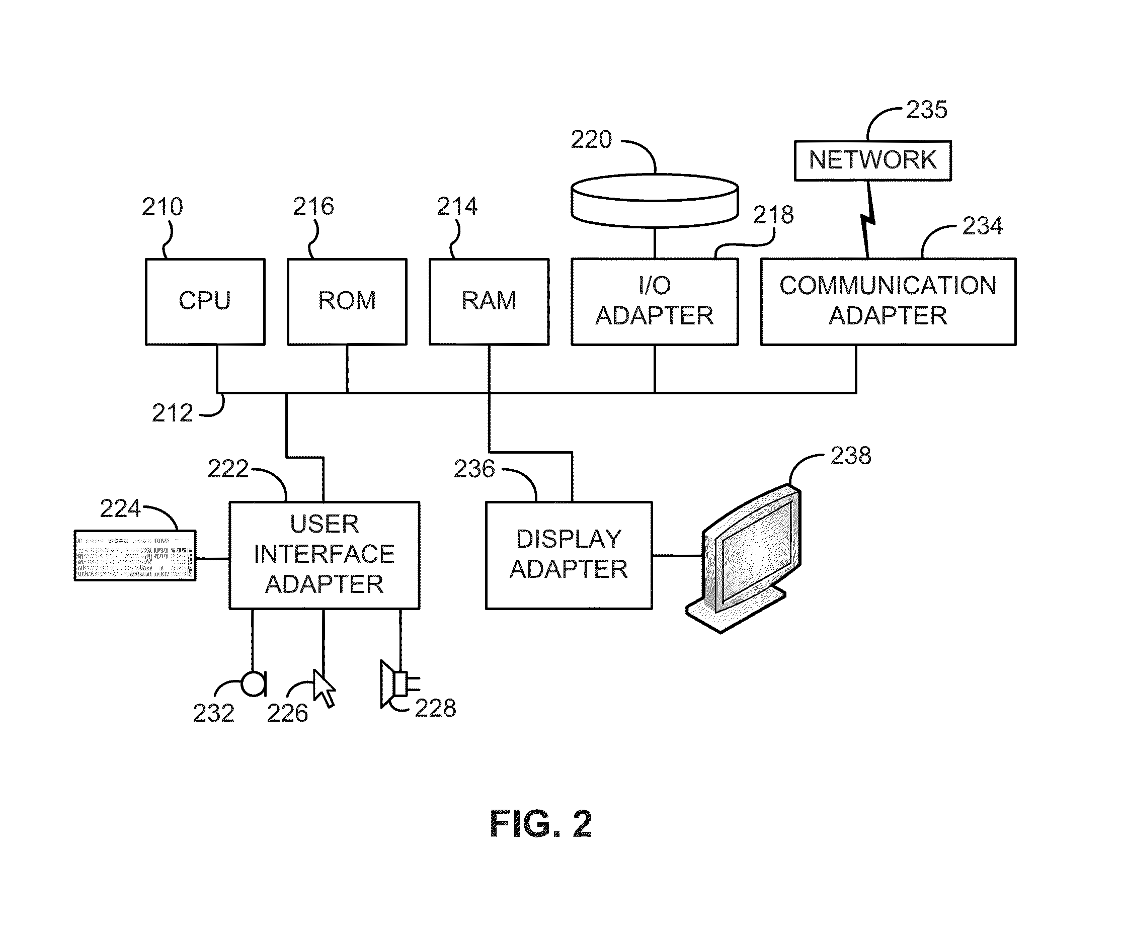
[0020]The following description is made for the purpose of illustrating the general principles of the present invention and is not meant to limit the inventive concepts claimed herein. Further, particular features described herein can be used in combination with other described features in each of the various possible combinations and permutations.

[0021]Unless otherwise specifically defined herein, all terms are to be given their broadest possible interpretation including meanings implied from the specification as well as meanings understood by those skilled in the art and / or as defined in dictionaries, treatises, etc.

[0022]It must also be noted that, as used in the specification and the appended claims, the singular forms “a,”“an” and “the” include plural referents unless otherwise specified. It will be further understood that the terms “comprises” and / or “comprising,” when used in this specification, specify the presence of stated features, integers, steps, operations, elements, a...


PUM


Abstract

In one embodiment, a method includes maintaining a first open logical erase block for user writes, maintaining a second open logical erase block for relocate writes, wherein the first and second open logical erase blocks are different logical erase blocks, receiving a first data stream having the user writes, transferring the first data stream to the first open logical erase block, receiving a second data stream having the relocate writes, and transferring the second data stream to the second open logical erase block. Other systems, methods, and computer program products are described in additional embodiments.

Description

BACKGROUND[0001]The present invention relates to data storage systems, and more specifically, this invention relates to solid-state drives separately allocating different write operations for improved separation of data and thereby reduced write amplification.[0002]Performance characteristics of conventional NAND flash-based solid state drives (SSDs) are fundamentally different from those of traditional hard disk drives (HDDs). Data in conventional SSDs is typically organized in pages of 4, 8, or 16 KB sizes. Moreover, page read operations are typically one order of magnitude faster than write operations and latency neither depends on the current nor the previous location of operations.[0003]However, memory locations must be erased in blocks prior to being written to. The size of an erase block unit is typically 256 pages and the erase operations takes approximately one order of magnitude more time than a page program operation. Due to the intrinsic properties of NAND flash, SSDs wr...

Claims


Application Information

Patent Timeline
IPC IPC(8): G06F12/02
CPCG06F12/0253G06F12/0246G06F2212/7205G06F2212/2022G06F2212/1036G06F2212/7211G06F3/0643G06F3/0616G06F3/0679G06F3/061G06F3/0631G06F3/064G06F3/0659G06F3/067
Inventor CAMP, CHARLES, J.FISHER, TIMOTHY, J.FRY, AARON, D.IOANNOU, NIKOLASKOLTSIDAS, IOANNISPLETKA, ROMANTOMIC, SASA
Owner IBM CORP
Learn More