Electrical connector with locking structures

a technology of locking structure and electrical connector, which is applied in the direction of coupling device connection, two-part coupling device, electrical apparatus, etc., can solve the problems of affecting the connection between the tails of the terminals and the pads, affecting the safety of mounting the electrical connector, and affecting the safety of the mounting of the electrical connector

Active Publication Date: 2016-03-31
OUPIN ELECTRONICS KUNSHAN
View PDF3 Cites 1 Cited by
  • Summary
  • Abstract
  • Description
  • Claims
  • Application Information

AI Technical Summary

Benefits of technology

[0008]The other object and the advantage of the present invention may be further understood from the technical features disclosed by the present invention.
[0009]To achieve the above object of the present invention, the present invention adopts the following technical solution.
[0010]The present invention provides an electrical connector with locking structures. The electrical connector comprises an insulation housing, two locking plates, multiple power terminals and multiple signal terminals. The insulation housing includes a mating portion located on the front thereof and a mounting portion located on the rear thereof. A front surface of the mating portion is perpendicular to a bottom surface of the mounting portion. The mating portion forms a receiving cavity extending backward from the front surface, and the mounting portion forms multiple power terminal-receiving passages and multiple signal terminal-receiving passages. The mounting portion further forms two locking structures, which are symmetrically disposed on two sides thereof and each of which includes a platform, a vertical fastener passage, a horizontal holding passage and a vertical block. The holding passage is formed under the platform and is parallel to the platform. The vertical block is located under the platform, and there forms a gap between the vertical block and a bottom s...

Problems solved by technology

But the welding force and the interference force can not ensure the mounting safety of the electrical connector.
Specifically, when the electrical connector is mated...

Method used


Image

  • Electrical connector with locking structures
  • Electrical connector with locking structures
  • Electrical connector with locking structures

Examples


Embodiment Construction

[0028]The following description of every embodiment with reference to the accompanying drawings is used to exemplify a specific embodiment, which may be carried out in the present invention. Directional terms mentioned in the present invention, such as “top”, “bottom”, “front”, “back”, “left”, “right”, “top”, “bottom” etc., are only used with reference to the orientation of the accompanying drawings. Therefore, the used directional terms are intended to illustrate, but not to limit, the present invention.

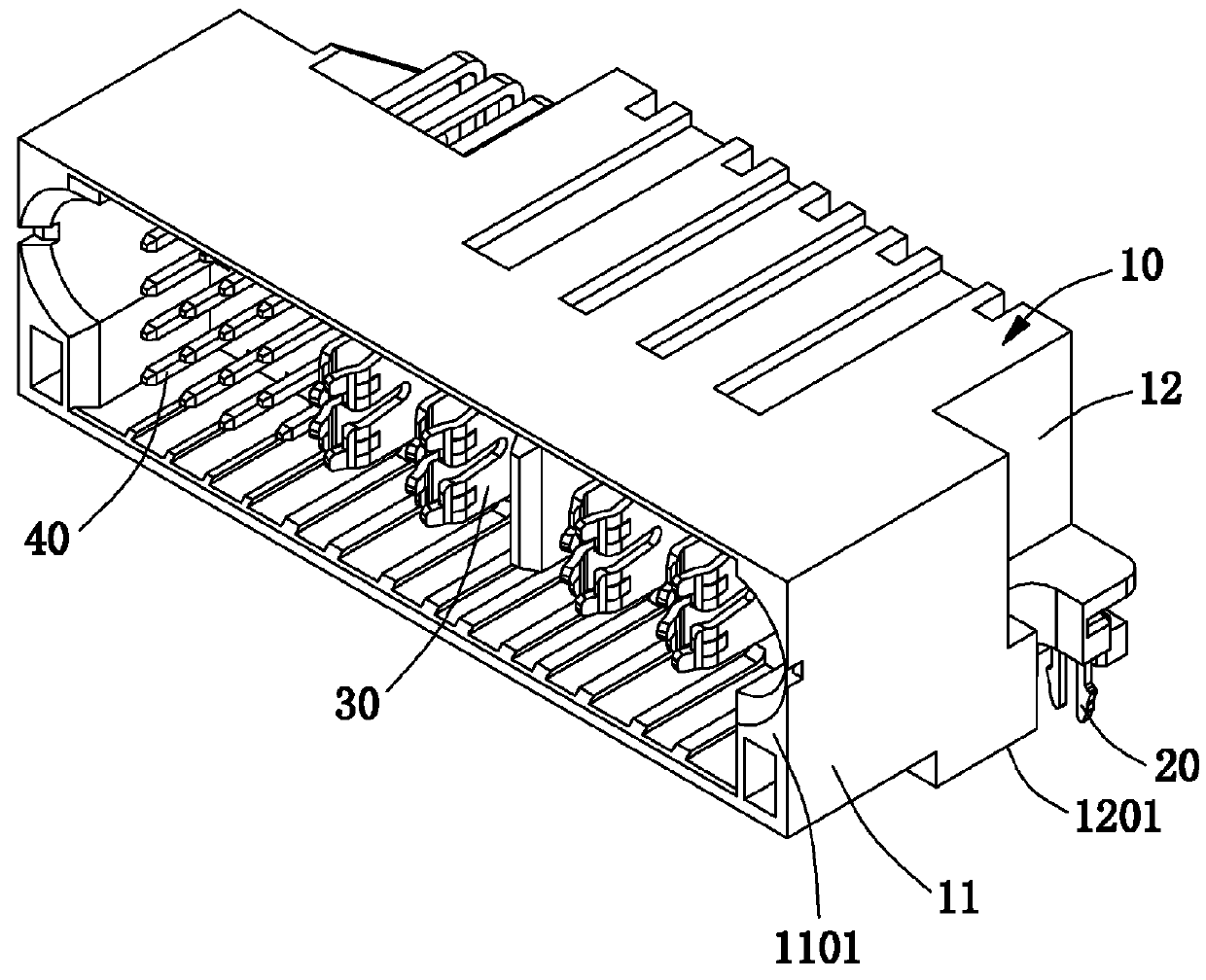
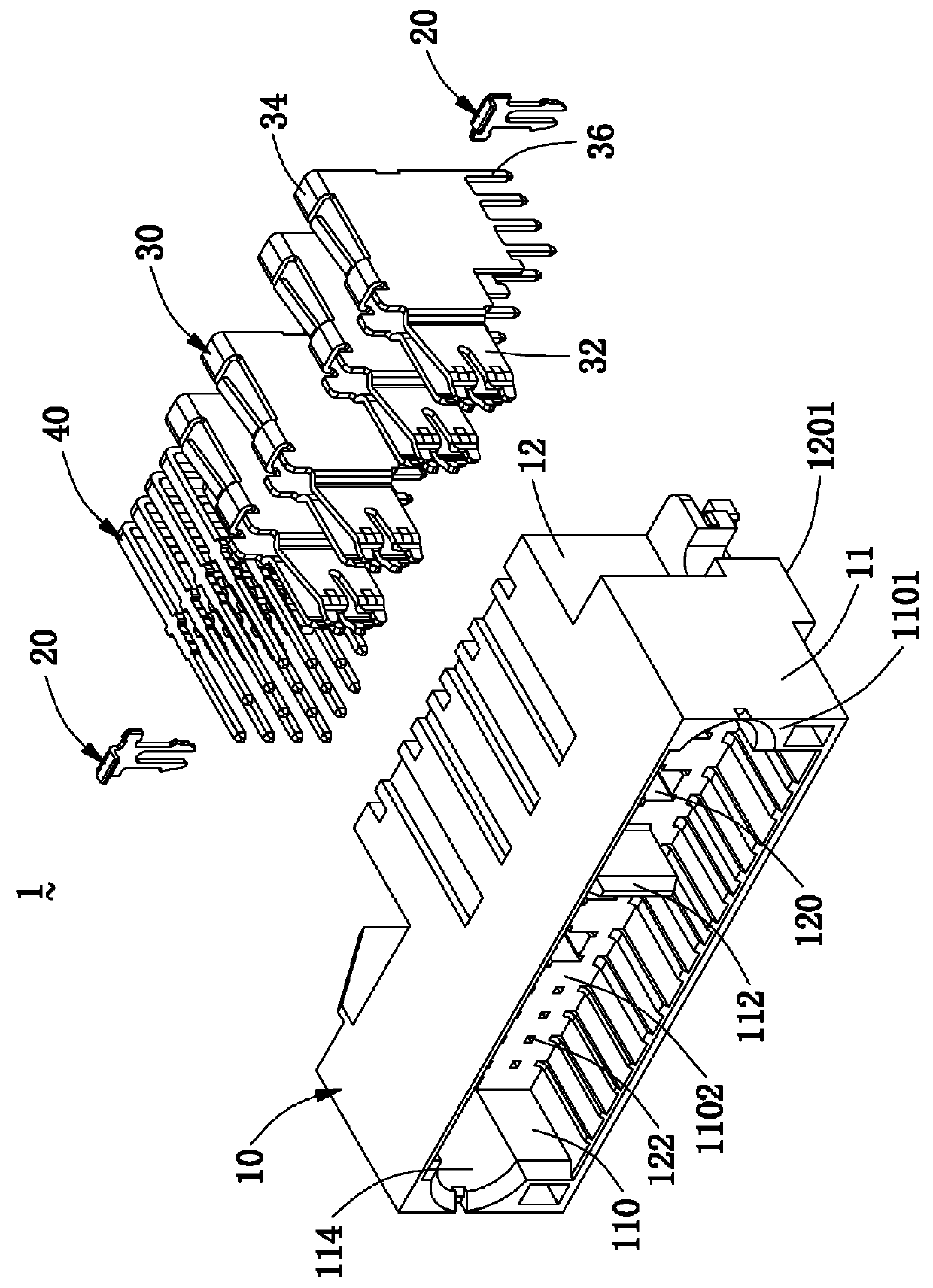
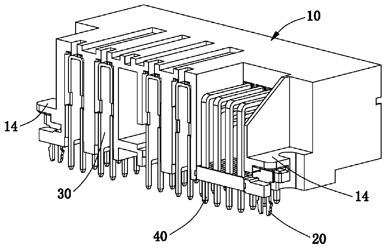
[0029]Please refer to FIGS. 1 to 7, FIG. 1 is a perspective schematic view of an electrical connector 1 with locking structures of the present invention; FIG. 2 is an exploded view of the electrical connector 1 of FIG. 1; FIG. 3 is a perspective schematic view of the electrical connector 1 along another direction; FIG. 4 is an exploded view of the electrical connector 1 of FIG. 3; FIG. 5 is an enlarged view of a locking structure 14 and a locking plate 20 of the electrical connector...


PUM


Abstract

An electrical connector with locking structures is disclosed. The electrical connector comprises an insulation housing, two locking plates, multiple power terminals and multiple signal terminals. The insulation housing forms two locking structures, each of which includes a platform, a vertical fastener passage, a horizontal holding passage and a vertical block. There forms a gap between the vertical block and a bottom support wall of the holding passage. Each locking plate is an L type and has a horizontal locking portion, a vertical locking portion and a locking foot. The horizontal locking portion is fixed in the holding passage, the vertical locking portion is clamped in the gap, and the locking foot is used to fix the electrical connector on a circuit board. The locking structure can ensure the locking plate to be fixed on a preset position, thereby protecting the electrical connector when using.

Description

BACKGROUND OF THE INVENTION[0001]1. Field of the Invention[0002]The present invention relates to a connector technology, and more particularly to an electrical connector with locking structures.[0003]2. Description of the Prior Art[0004]Generally, one electrical connector is fixed on a circuit board by using a SMT (Surface Mounted Technique) way and depends on a welding force between tails of terminals of the electrical connector and pads of the circuit board. The other electrical connector is fixed on the circuit board by using a through-hole fixing way and depends on an interference force between tails of terminals of the electrical connector and welding holes of the circuit board. But the welding force and the interference force can not ensure the mounting safety of the electrical connector. Specifically, when the electrical connector is mated with a complementary connector, the insertion force will damage the connection between the tails of the terminals and the pads or the weld...

Claims


Application Information

Patent Timeline
IPC IPC(8): H01R13/627H01R24/66
CPCH01R13/6273H01R2107/00H01R24/66H01R12/724H01R12/7029
Inventor CHEN, HSIN, CHIH
Owner OUPIN ELECTRONICS KUNSHAN
Why Eureka
Try Eureka